Vanguard WRM-10 User Manual
Page 12
WRM-10 USER’S MANUAL
REV 2
9
3.0 OPERATING
PROCEDURES
3.1
WRM-10 Cable Connections
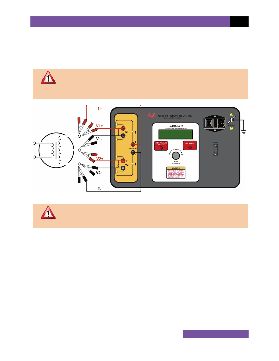
Typical WRM-10 connections diagrams are shown in Figure 5 and Figure 6. A typical dual
winding connections diagram is shown in Figure 7.
WARNING
Do not touch or disconnect any test lead that is connected to a transformer
terminal while high current is being conducted during a test. Failure to heed this
warning can result in lethal electric shock to personnel and/or damage to the
equipment.
Figure 5. Typical WRM-10 Connections Diagram #1
WARNING
Disconnect the test clips from the transformer bushing only after the WRM-10
has completely discharged the transformer. Always disconnect the test clips
slowly from the transformer bushing to prevent an accidental flash-over.
- Resistor Transducer Adapter 9095-UC (7 pages)
- Accu-Ohm 200 S2 (4 pages)
- Accu-Trans (28 pages)
- ATO-400 (43 pages)
- ATO-400P (44 pages)
- Auto-Ohm (22 pages)
- Auto-Ohm 100_200 s2 (31 pages)
- Auto‐Ohm 200 S3 (66 pages)
- DMOM-100 (35 pages)
- DMOM-100_200 s2 (42 pages)
- DMOM-200 (33 pages)
- Herculito (17 pages)
- ATRT-01 S2 (59 pages)
- ATRT-01_01B S3 (88 pages)
- ATRT-01_01B_01D (31 pages)
- ATRT-03_03A (114 pages)
- ATRT-03_03A S2 (147 pages)
- CVT-765 (46 pages)
- Tri-Phase (155 pages)
- CBCT (14 pages)
- CBPS-300 (16 pages)
- CT-3500 (24 pages)
- CT-3500 S2 (53 pages)
- CT-6500 (69 pages)
- CT-6500 S2 (82 pages)
- CT-7000 (83 pages)
- CT-7000 S2 (108 pages)
- CT-7000 S3 (137 pages)
- CT-7500 (76 pages)
- CT-7500 S2 (110 pages)
- CT-8000 (120 pages)
- CT-8000 S3 (145 pages)
- DigiTMR (86 pages)
- DigiTMR S2 (123 pages)
- DigiTMR S2 PC (31 pages)
- MCCB-250 (17 pages)
- UPS S2 (13 pages)
- EZCT-2000 (68 pages)
- EZCT-2000 (45 pages)
- EZCT-2000A (103 pages)
- EZCT-2000B (118 pages)
- EZCT-2000C Plus (119 pages)
- EZCT-S2 (66 pages)
- EZCT-S2A (98 pages)
- IRM-5000P (58 pages)