Vanguard ATRT-01_01B_01D User Manual
Page 8
Model ATRT-01 (v) Operating Instructions
Rev 02
May 02, 2002
7
7.0 ATRT-01 Operating Controls And Indicators
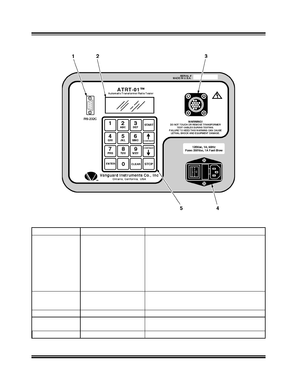
Figure 7-0. Model ATRT-01 Front-Panel Controls, Indicators, and Connectors
Fig. 7-0 Index
Panel Markings
Functional Description
1
RS-232C
Computer-Interface port, 9-pin, female DB type
connector; RS-232C interface port allows ATRT-01
to interface with an IBM computer. Data rate is set to
19,200 baud, 1 start bit, 8 data bits, 2 stop bits, and
no parity bit. Connector pin functions are:
PIN SIGNAL
2 Tx
3 Rx
5 Gnd
2
None (display)
LCD screen: 4 line by 20 character; back-lighted,
sunlight readable; Displays menus, test results, and
status readouts.
3
None
High and Low voltage connector, 16-pin male.
4
120/220Vac, 1A, 50/60Hz
Input power connector and fused power switch with
third-wire safety ground.
5
None (Keypad)
Pushbutton operating controls, 16-keys.
- Resistor Transducer Adapter 9095-UC (7 pages)
- Accu-Ohm 200 S2 (4 pages)
- Accu-Trans (28 pages)
- ATO-400 (43 pages)
- ATO-400P (44 pages)
- Auto-Ohm (22 pages)
- Auto-Ohm 100_200 s2 (31 pages)
- Auto‐Ohm 200 S3 (66 pages)
- DMOM-100 (35 pages)
- DMOM-100_200 s2 (42 pages)
- DMOM-200 (33 pages)
- Herculito (17 pages)
- ATRT-01 S2 (59 pages)
- ATRT-01_01B S3 (88 pages)
- ATRT-03_03A (114 pages)
- ATRT-03_03A S2 (147 pages)
- CVT-765 (46 pages)
- Tri-Phase (155 pages)
- CBCT (14 pages)
- CBPS-300 (16 pages)
- CT-3500 (24 pages)
- CT-3500 S2 (53 pages)
- CT-6500 (69 pages)
- CT-6500 S2 (82 pages)
- CT-7000 (83 pages)
- CT-7000 S2 (108 pages)
- CT-7000 S3 (137 pages)
- CT-7500 (76 pages)
- CT-7500 S2 (110 pages)
- CT-8000 (120 pages)
- CT-8000 S3 (145 pages)
- DigiTMR (86 pages)
- DigiTMR S2 (123 pages)
- DigiTMR S2 PC (31 pages)
- MCCB-250 (17 pages)
- UPS S2 (13 pages)
- EZCT-2000 (68 pages)
- EZCT-2000 (45 pages)
- EZCT-2000A (103 pages)
- EZCT-2000B (118 pages)
- EZCT-2000C Plus (119 pages)
- EZCT-S2 (66 pages)
- EZCT-S2A (98 pages)
- IRM-5000P (58 pages)