Installation instructions - sheet 1 nbox/einc, 3 installation - mounting, Connect ethernet – TREND NBOX_EINC User Manual
Page 3: 2 wire connect current loop, 4 wire, Close flap
1 - 3
NBOX/EINC Installation Instructions TG200152 Issue 2/D 4/7/06
Installation Instructions - Sheet 1
NBOX/EINC
X
T
T
R
R
T- T+ R- R+
9 10
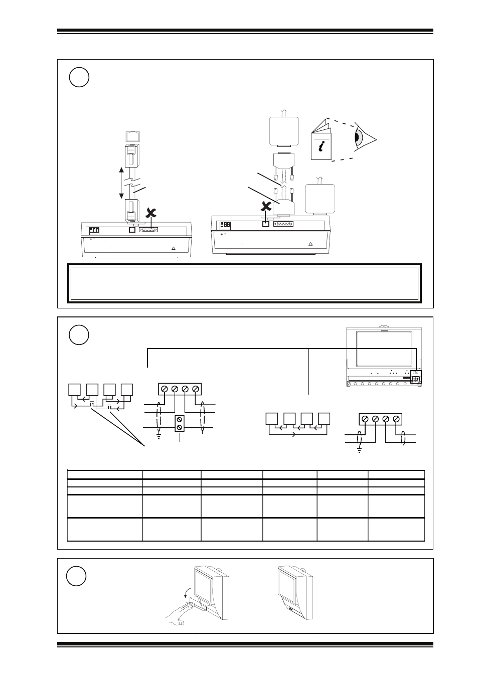
1.3 INSTALLATION - MOUNTING
(Continued)
~
2 3 0 V
R D S / R S 2 3 2
!
2 4 V
~
M O D E M
using AUI
Transceiver
OR
~
2 3 0 V
R D S / R S 2 3 2
!
2 4 V
~
M O D E M
15 way D
type Male
no connection
Drop cable
100 m (110 yds)
Ethernet hub/switch
10BASE-T
RJ45 Connector
no connection
RJ45 Connector
Connect Ethernet
6
Connect to an Ethernet hub
Use Ethernet cable.
IQ System
Products
Engineering
Guide TE200369
T R
T R
T R
T R
T R
T R
T R
T R
2 wire
Connect Current Loop
7
4 wire
Additional terminals
Note only 1 INC type node on a single Lan.
Maximum Cable distance
Terminal size 0.5 to 2.55
m
2
(14 to 20 AWG)
Cable
1k2 baud
9k6 baud
19k2 baud
38k4 baud *
No. of Wires
Belden 9182
1000 m (1090 yds) 1000 m (1090 yds)
700 m (765 yds)
500 m (545 yds)
2
Belden 9207
1000 m (1090 yds) 1000 m (1090 yds)
500 m (545 yds)
350 m (380 yds)
2
IQ System
TP/1/1/22/HF/200
(Belden 8761)
1000 m (1090 yds) 700 m (765 yds)
350 m (380 yds)
250 m (270 yds)
2
IQSystem
TP/2/2/22/HF/200
(Belden 8723)
1000 m (1090 yds) 500 m (545 yds)
250 m (270 yds)
125 m (135 yds)
4
X
T
T
R
R
T
T
R
R
T- T+ R- R+
Terminal size 0.5 to 2.55
m
2
(14 to 20 AWG)
Close Flap
8
a
b
IMPORTANT
EINCs do NOT support automatic addressing, and MUST NOT be installed on an Ethernet network where automatic
addressing is being used.
Transceiver