Installation instructions - part 2 kit/nodeiq23x, Connect to lonworks, Check settings – TREND KIT_NODE_IQ23x User Manual
Page 7: Switch on, Check node controller
Installation Instructions - Part 2
KIT/NODEIQ23x
KIT/NODE/IQ23x Node Fixing Kit Installation Instructions TG200570 Issue 1/A 31/5/02
2 - 3
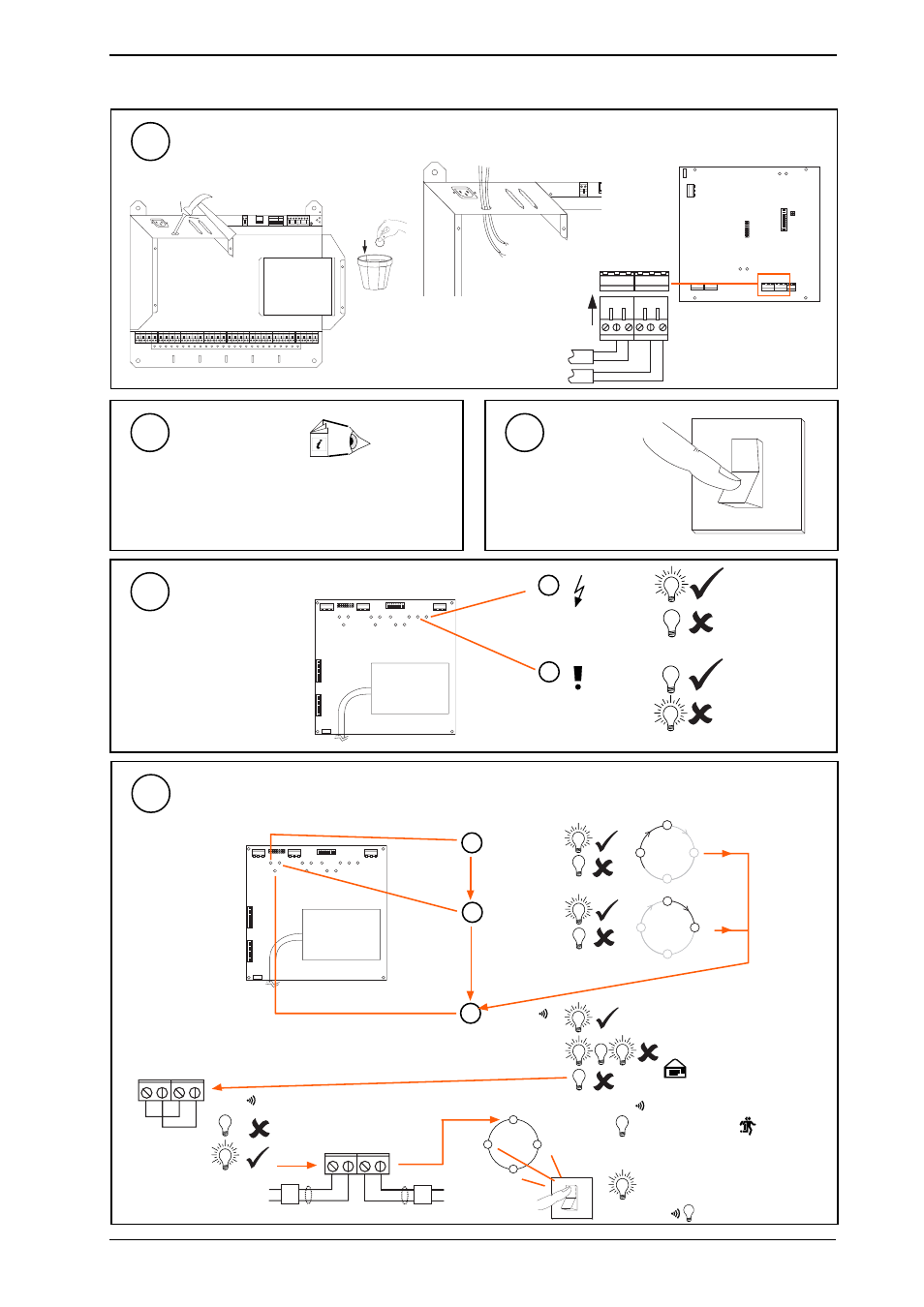
2 Installing a Node in IQ23x using KIT/NODE/IQ23x - Part 2
(continued)
Connect to LonWorks
25
R X
T X
O K
1
2
8
4
16
32
64
1K
2
9K
6
19
K
2
A D D R E S S
B A U D
(a)
Knock out hole
(c)
Connect Lon cables
(b)
Push cables through hole
J 1 5
J 1
L A N
P
O
W
E
R
J 1 1
9
10
J 1 2
J 9
J 1 7
Check Settings
26
(a)
Check network baud rate.
(b)
Check network address and dumb/normal switch.
(c)
Check 2nd network/device baud rate.
Node
Controller Data
Sheet
Switch On
27
O
1
Check Node Controller
28
SCN
LanA
LanB
SCN
LanA
LanB
J7
E
T1
J1
6
D
ev
B
J1
5
D
ev
A
J9
J8
La
n
B
La
n
A
M
od
em
TMN type board shown
Check data sheet for
location of LEDs on other
boards
b
W/DOG
(red)
a
PWR ON
(green)
Check supply
Node Faulty
if appropriate
O
I
I Q 2 3 x
?
I Q 2 3 x
?
T X -
T X +
R X - R X +
T X -
T X +
R X - R X +
b
TX
(yellow)
a
RX
(yellow)
c
OK
(green)
Node Faulty
Check baud rate
. Check
network cabling for short circuits
with a multimeter (NOT Megger)
Network Address Invalid
0, 2, 3 or >119
OK
OK
node
Power up other nodes until
faulty node is found
(OK
). Correct fault.
Check Trend Lan and Internetwork sections
Do separate check fo each Lan/Internetwork segment
29
J7
E
T1
J1
6
D
ev
B
J1
5
D
ev
A
J9
J8
La
n
B
La
n
A
M
od
em
TMN type board
shown
Check data sheet
for location of
LEDs on other
boards
node
node
For LINC only
LAN
LAN