Installation instructions encls/... enclosures, Installation – TREND ENCLS_... User Manual
Page 2
Installation Instructions
ENCLS/... ENCLOSURES
2 ENCLS/... Enclosures Installation Instructions TG103175 Issue 1/A 1/7/96
Trend Control Systems Ltd reserves the right to revise this publication from time to time and make changes to the content hereof
without obligation to notify any person of such revisions or changes.
Trend Control Systems Ltd. P.O. Box 34 Horsham Sussex RH12 2YF England Tel:+44 (0)1403 211888 Fax:+44 (0)1403 241608 www.trend-controls.com
Installation
(Continued)
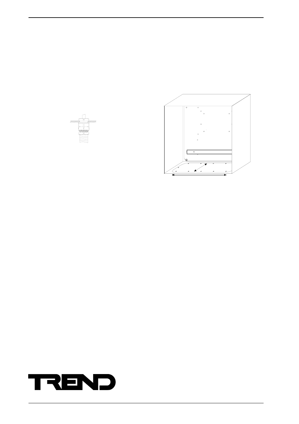
Route any cables
(7)
Drill 20 mm holes for M20 copex type cable glands
in the positions required in the gland plate
(8)
Route the cables for the I/O, network, and
controller power into the enclosure through the
cable glands.
Install the controller
(9)
Complete the installation of the controller or NETB
as described in the relevant installation
instructions.
530 mm
150 mm
use copex glands
Note that the DIN rail may be used for mounting relay modules
(2RM etc) or other interface nodes (e.g. 4DIX etc).