Installation instructions tb/ts/k installation, If iq, If iql – TREND TB_TS_K User Manual
Page 3: Wire to controller, Continued), 14 to 20 awg), Analogue inputs linked for thermistor (t)
TB/TS/K Thermistor Room Temperature Sensors Installation Instructions TG200607 Issue 1/D 29/03/07
3
Installation Instructions
TB/TS/K
INSTALLATION
(continued)
Wire to controller
7
if IQ
1 2 3
TB/TS
2 1 2 2
1
C O M
I Q L 1 2 , 1 4
2
1
1
2
3
TB/TS
/K
C O M
2 1 2 2 2 3 2 4 2 5 2 6 2 7 2 8
C O M
1
2
3
4
5
C
I Q L 1 3 + , 1 5 + , 1 6
0 V
T e m
p e r a t u r e
K n o b
1
2
3
I N
I N
C O M ( 0 V )
S E N S O R
I Q 2
T B / T S
/ K
C O M ( 0 V )
if IQL
TB/TS
C O M
9
10
1
I Q L 1 0 / 2 4 V A C
2
1
TB/TS
1 5 1 6
1
C O M
I Q L 1 0 / 2 3 0
2
1
TB/TS
9
1 0
1
1 1
1 2
1 3
3
C O M
C
2
I Q L 1 1 + / 2 4 V A C
3
2
1
/K
TB/TS
C O M
1 5 1 6 1 7 1 8 1 9
1
2
3
C
I Q L 1 1 + / 2 3 0
1
2
3
/K
N
O
I
T
P
O
S
L
A
N
I
M
R
E
T
T
C
E
N
N
O
C
S
T
/
B
T
2
,
1
K
/
S
T
/
B
T
3
,
2
,
1
L
Q
I
S
N
O
I
T
P
O
4
1
,
2
1
,
0
1
L
Q
I
S
T
/
B
T
7
1
,
6
1
,
+
5
1
,
+
3
1
,
+
1
1
L
Q
I
K
/
S
T
/
B
T
,
S
T
/
B
T
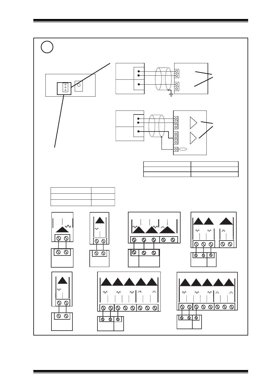
Note that screened cable is not required for sensor
wiring to IQLs. If screened cable is used, the
screen must be terminated at the controller to its
supply cable earth.
Terminal size 0.5 to 2.5 mm
2
(14 to 20 AWG)
1
2
3
TB/TS
/K
C O M
2 1 2 2 2 3 2 4 2 5 2 6 2 7 2 8
1
2
3
4
5
C
0 V
A I
1 0 V
I Q L 1 7
0 V
T e m
p e r a t u r e
K n o b
1
2
3
N ( i n )
S E N S O R
I Q 3
T B / T S
/ K
0 ( 0 V )
+ ( + 2 4 V )
N ( i n )
0 ( 0 V )
+ ( + 2 4 V )
N
N + 1
analogue inputs
linked for
thermistor (T)
analogue inputs
linked for
thermistor (T)