Iql only, Wire to controller, Assemble unit – TREND TB_TS_KE, _KEF User Manual
Page 3
TB/TS/KE, /KEF Sensors Installation Instructions TG200605 Issue 1/D 14/02/07
3
Installation Instructions
TB/TS/KE, /KEF
INSTALLATION
(continued)
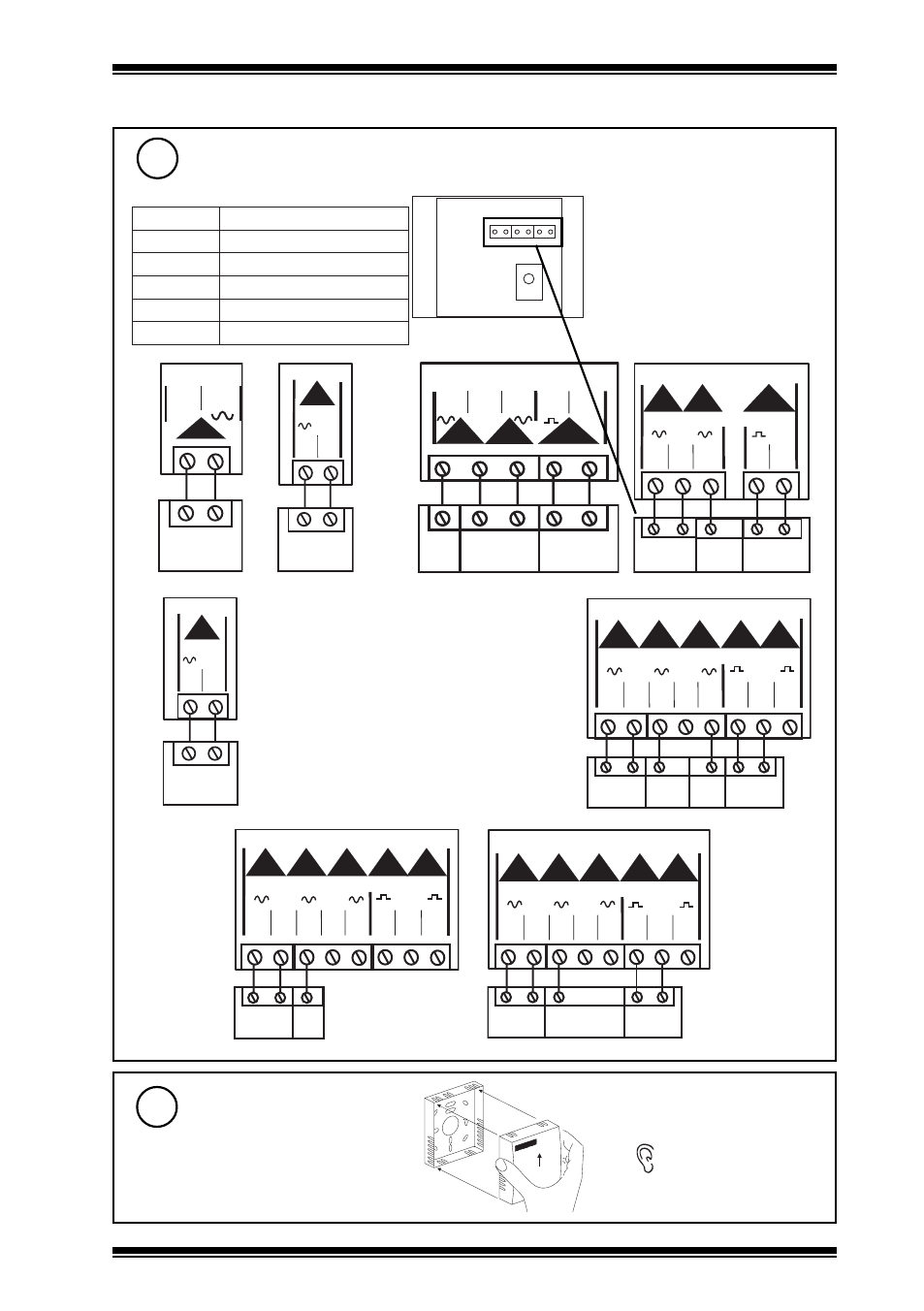
Wire to controller
7
IQL only
1 2 3 4 5 6
Note that these options
(TB/TS/KE, or TB/TS/KEF) cannot
be used with IQs or FCs; use
options TB/TS, TB/TS/K, /KO, /
OS, /KOF, or /KOSF with IQs or
FCs.
TB/TS
C O M
9
10
1
I Q L 1 0 / 2 4 V A C
1
2
TB/TS
1 5 1 6
1
C O M
I Q L 1 0 / 2 3 0
1
2
3
2
1
5
4
TB/TS
/K
/E
9
1 0
1
1 1
1 2
1 3
3
C O M
C
2
I Q L 1 1 + / 2 4 V A C
1
2
3
5
4
TB/TS
/K
/E
C O M
1 5 1 6 1 7 1 8 1 9
1
2
3
C
I Q L 1 1 + / 2 3 0
TB/TS
2
1
C O M
I Q L 1 2 , 1 4
1
2 1
2 2
1
2
3
6
5
4
TB/TS
/K
/E
/F
C O M
2 1 2 2 2 3 2 4 2 5 2 6 2 7 2 8
C O M
1
2
3
4
5
C
I Q L 1 3 + , 1 5 +
1
2
3
5
4
TB/TS
/K
/E
C O M
2 1 2 2 2 3 2 4 2 5 2 6 2 7 2 8
1
2
3
4
5
C
0 V
A I
1 0 V
I Q L 1 7
Note that screened cable is not required
for sensor wiring to IQLs.
If screened cable is used, the screen
must be terminated at the controller to
its supply earth.
1
2
3
TB/TS
/K
C O M
2 1 2 2 2 3 2 4 2 5 2 6 2 7 2 8
C O M
1
2
3
4
5
C
I Q L 1 6
Terminal size 0.5 to 2.5 mm
2
(14 to 20 AWG)
L
Q
I
S
N
O
I
T
P
O
4
1
,
2
1
,
0
1
L
Q
I
S
T
/
B
T
7
1
,
+
1
1
L
Q
I
E
K
/
S
T
/
B
T
,
K
/
S
T
/
B
T
,
S
T
/
B
T
+
3
1
L
Q
I
F
E
K
/
S
T
/
B
T
,
E
K
/
S
T
/
B
T
,
K
/
S
T
/
B
T
,
S
T
/
B
T
+
5
1
L
Q
I
F
E
K
/
S
T
/
B
T
,
E
K
/
S
T
/
B
T
,
K
/
S
T
/
B
T
,
S
T
/
B
T
6
1
L
Q
I
K
/
S
T
/
B
T
,
S
T
/
B
T
Assemble unit
8
‘click’