Receiver test calibration – Teledyne LeCroy QPHY-USB3-Tx-Rx User Manual
Page 36
36
917719 Rev
A
At the completion of this part of the Differential Voltage & De-emphasis Test the oscilloscope is in the following
configuration:
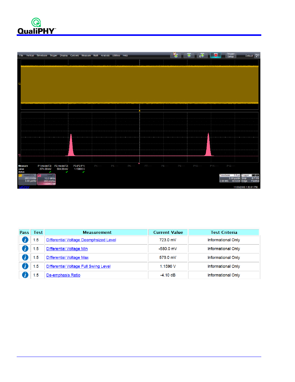
Figure 28 - Oscilloscope Configuration after Differential Voltage & De-emphasi s Test on CP8
On the screen are 2 visible traces. The first is the result of the ac quisition of the CP 8 signal after (optional) cable
de-embedded has been performed. The second is the histogram created from this signal. P1 and P2 are the 2
modes of the histogram. These 2 parameters only differ in the measurement gates that have been set . P3 is the
difference of the 2 modes.
Figure 29 - Test Report from Differential Voltage & De -emphasi s Test
Receiver Test Calibration
As of the release of this version of QP HY-USB 3-Tx-Rx, the receiver test calibration portion of the specific ation has
not yet been fully defined. For this reason, this test gives the user the ability to manually set their own jitter
parameters that the PeRT
3
uses during each of the 8 points of the jitter tolerance test . The existing calibration
settings are loaded for the user. These values can be verified using the SDA II software and modified as
necessary. If the user modifies the values, they are saved for fut ure use. For additional information, refer to the
Receiver Test Calibration section of this manual.