Test 1.4 ac and dc common mode voltage tests, Test 1.5 differential voltage & de-emphasis test – Teledyne LeCroy QPHY-USB3-Tx-Rx User Manual
Page 34
34
917719 Rev
A
Test 1.4 AC and DC Common Mode Voltage Tests
The purpose of this test group is to verify that the AC and DC common mode voltages are within the specification
limits. The AC Common Mode Voltage is defined as the peak-to-peak Voltage of the common mode signal and
the DC Common Mode Volt age is defined as the mean voltage of the common mode signal.
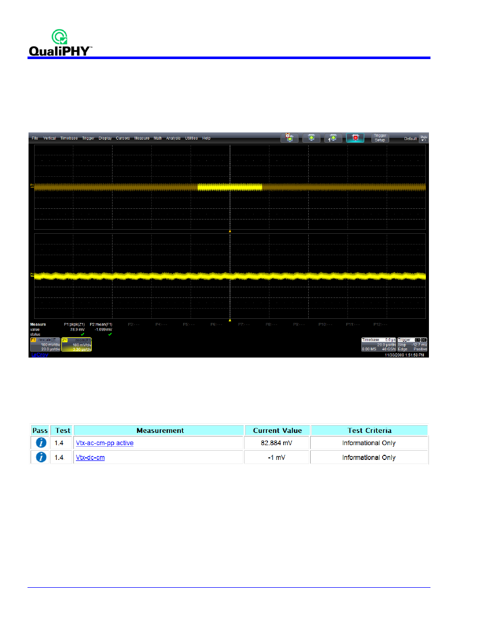
At the completion of the AC and DC Common Mode Voltage Test the oscilloscope is in the following
configuration:
Figure 25 - Oscilloscope Configuration after AC and DC Common Mode Test
On this screen there are 2 traces visible. In F1, the 2 input channels are added together and divided by 2 to
yield the common mode trace. In Z1, we show a zoom of this trace. The A C Common mode is calculated by
measuring the peak -to-peak value of this zoom trace (P1). The DC Common mode measurement is made over a
longer interval of time and is calculated by measuring the mean value of F1, the complete trac e (P2).
Figure 26 - Test Report from AC and DC Common Mode Test
Test 1.5 Differential Voltage & De-emphasis Test
The purpose of this test is to verify that the Differential Voltage and De -emphasis are within the speci fication
limits. These 2 tests are performed together in 2 steps. The first step acquires the CP7 complianc e pattern . This
pattern consists of 50-
250 1’s followed by 50-250 0’s with de-emphasis applied to the signal. Once this acquisition
is performed, a histogram is created from the data. The difference bet ween the 2 modes of the histogram is
calculated and is the amplitude of the de-emphasized bits.