Teledyne LeCroy AGPAX User Manual
Page 5
5
EXTERNAL POWER SUPPLY
An external terminal J5 is used for the external power supply input. However remember never to connect any supply to
these inputs so long as you have JP5, JP6, JP7, and JP9 installed. In case you want to use the external supply as an
input you must remove these 4 jumpers in order not to cause any conflict with the bus voltages. These jumpers are,
however, independent from each other. For instance if you would want to bring in only a +5V from the external supply
and continue to use the bus voltages for +12V, VCC3 and VDDQ, you would only need to remove JP5. The list below
identifies which jumper is for which supply:
JP5 = +5V
JP6 = +12V
JP7 = VCC3
JP9 = VDDQ
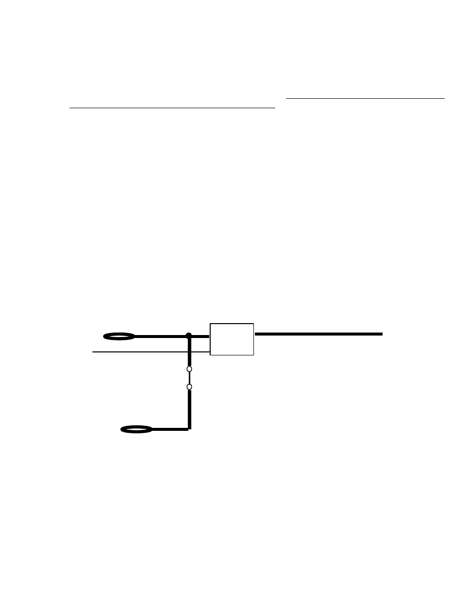
The following diagram indicates the interconnection of the Unit-Under-Test voltages to the bus voltages and the
external voltages:
VCC3 (external)
On-Off
VCC3 out to UUT
Base Address, 50 or 05
VCC3 Out
JP7
VCC3 (from the bus)
As you can see, there will be conflict in case the external supply is connected while the jumper is still in place. This
circuit is repeated for each of the 4 voltages.
If you are using external power supplies do not forget to connect the Ground (GND) signals between the system and the
supply. If your external power supply outputs are not isolated, make sure the ground of the PC (containing the extender
board) and the ground of the power supply are at the same voltage phase/level with respect to a common point, before
connecting the GND signal.