Installing the software, Setting up the analyzer, Description – Teledyne LeCroy Voyager M3 Quick Start Guide User Manual
Page 2
Installing the Software
Note: You must install the software before connecting the Analyzer to the host machine for the first time.
1.
Insert the Installation CD into the CD drive on the host PC.
2.
Select Install Software from the Installation CD and follow the on-screen installation instructions to install the application on the PC
hard disk.
Setting Up the Analyzer
To set up the Analyzer:
1.
Connect the AC power cable to the rear of the Analyzer and
to a 100-volt to 240-volt, 50-Hz to 60-Hz, 100-W power outlet.
2. Connect the USB port to a USB port on the PC using the
LONG (6-foot/2-meter) USB cable.
3.
Insert the Installation CD.
4.
Turn on the power switch.
At power-on, the Analyzer initializes itself in approximately
ten seconds and performs an exhaustive self-diagnostic that
lasts about five seconds.
5.
Click Next after you see the Add New Hardware Wizard
window.
6.
Follow the Microsoft
®
Windows
®
on-screen Plug-and-Play
instructions for the automatic installation of the Analyzer as a
USB device on your analyzing PC (the required USB files are
included on the Installation CD)
7.
Click Finish when you see the message that says “Windows
has finished installing the software that your new hardware
requires” and the file lvoyager.inf has been installed in your
PC.
Note: Check Analyzer setup in the next section.
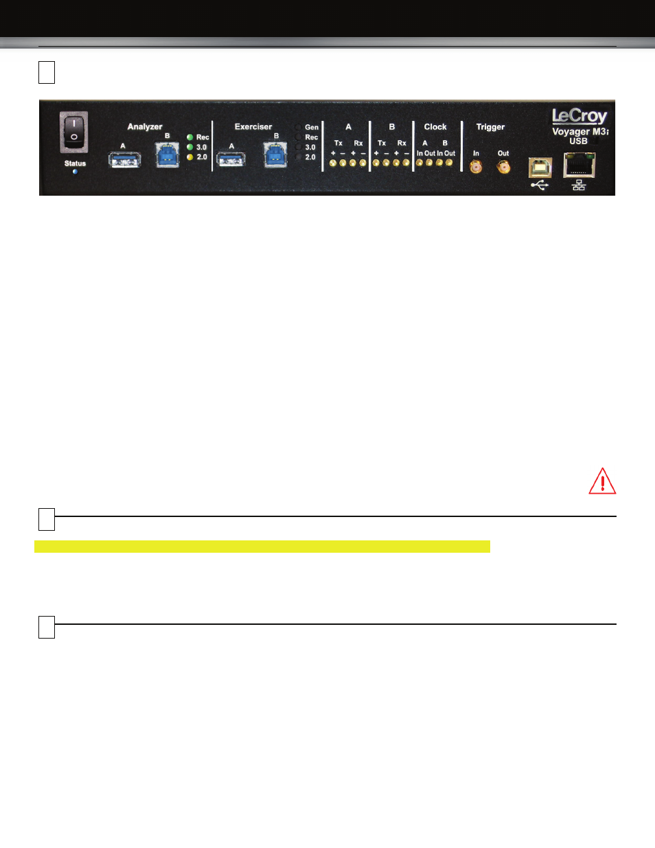
The Analyzer has the following indicators and connectors:
Power Switch (0/1)
Status LED (blue if system successfully initializes)
(red if hardware failure)
(green while initializing)
Analyzer Ports A (downstream) and B (upstream)
Analyzer LEDs
Rec - Recording (red if recording enabled)
3.0 - USB 3.0
(green if traffic detected)
2.0 - USB 2.0
(yellow for Low and Full Speed)
(green for Hi Speed)
Exerciser Ports A (downstream) and B (upstream)
Exerciser LEDs
Gen- Generating (green if generating enabled)
Rec - Recording (red if recording enabled)
3.0 - USB 3.0
(green if traffic detected)
2.0 - USB 2.0
(yellow for Low and Full Speed)
(green for Hi Speed)
A (downstream) - MMCx plug connectors for interfacing
B (upstream)
with USB 3.0 signals
Tx +- (Transmit pair)
Rx +- (Receive pair)
Clock A (downstream) - MMCx plug connectors for interfacing
Clock B (upstream)
with external clock source or sink
In - Connects to an external reference clock.
Out - Provides reference clock output.
Trigger
In - SMA external trigger input.
Out - SMA external trigger output.
USB
- Type B connector for connection to host computer
ETHERNET - Gigabit Ethernet for connection to host computer
Note: The rear panel has only a power connector.
Warning:
Do not open the Voyager M3i enclosure. No
operator serviceable parts are inside. Refer
servicing to LeCroy customer care.
3
4
5
Description