Setting up the analyzer, Front panel description, Rear panel description – Teledyne LeCroy UWBTracer Getting Started Guide User Manual
Page 2: Installing the software
Setting Up the Analyzer
Note: You must install the software before connecting the
analyzer to the host machine for the first time.
To set up the analyzer:
1.
Remove the UWBTracer/Trainer analyzer, external power
supply, and power cord from the shipping container or
carrying case.
2. Ensure that the analyzer plug-in is in the right-hand slot and
the exerciser plug-in is in the left-hand slot (as seen with the
front panel facing you).
3.
Connect the analyzer to the power supply. Connect the power
cord to the power supply. Connect the power cord to a
100V–240V, 50Hz–60Hz, power outlet to turn on the
analyzer (the power supply and the analyzer have no switch).
Note: It is not recommended to connect the analyzer to the
power supply after connecting the power supply cord to a
power outlet.
At power on, the Status LED of the CATC 5K platform turns
green and remains on 20 seconds while the analyzer
performs self-diagnosis.
If the diagnostics pass, the Status LED turns blue.
If the diagnostics fail, the Status LED blinks red to indicate
hardware failure (call Customer Support).
4.
Connect the USB cable between the HOST USB port on the
back of the analyzer and a USB port on the PC. The host
operating system detects the analyzer and begins to install
the USB driver.
5.
Step through the Microsoft
®
Windows
®
hardware wizard. The
wizard automatically installs UWBTracer/Trainer as a USB
device on the PC. The required USB driver files catc5k.sys
and uwb5k.sys were placed in the correct directory during
software installation.
For synchronized multi-analyzer operation, the analyzers
must be connected in a daisy-chain topology to each other
using the Green/Purple cable.
Front Panel Description
FPO only RF CH 1 RF CH 0
STATUS (status of the platform)
MPI/RF (status of the MPI or RF Analyzer channel)
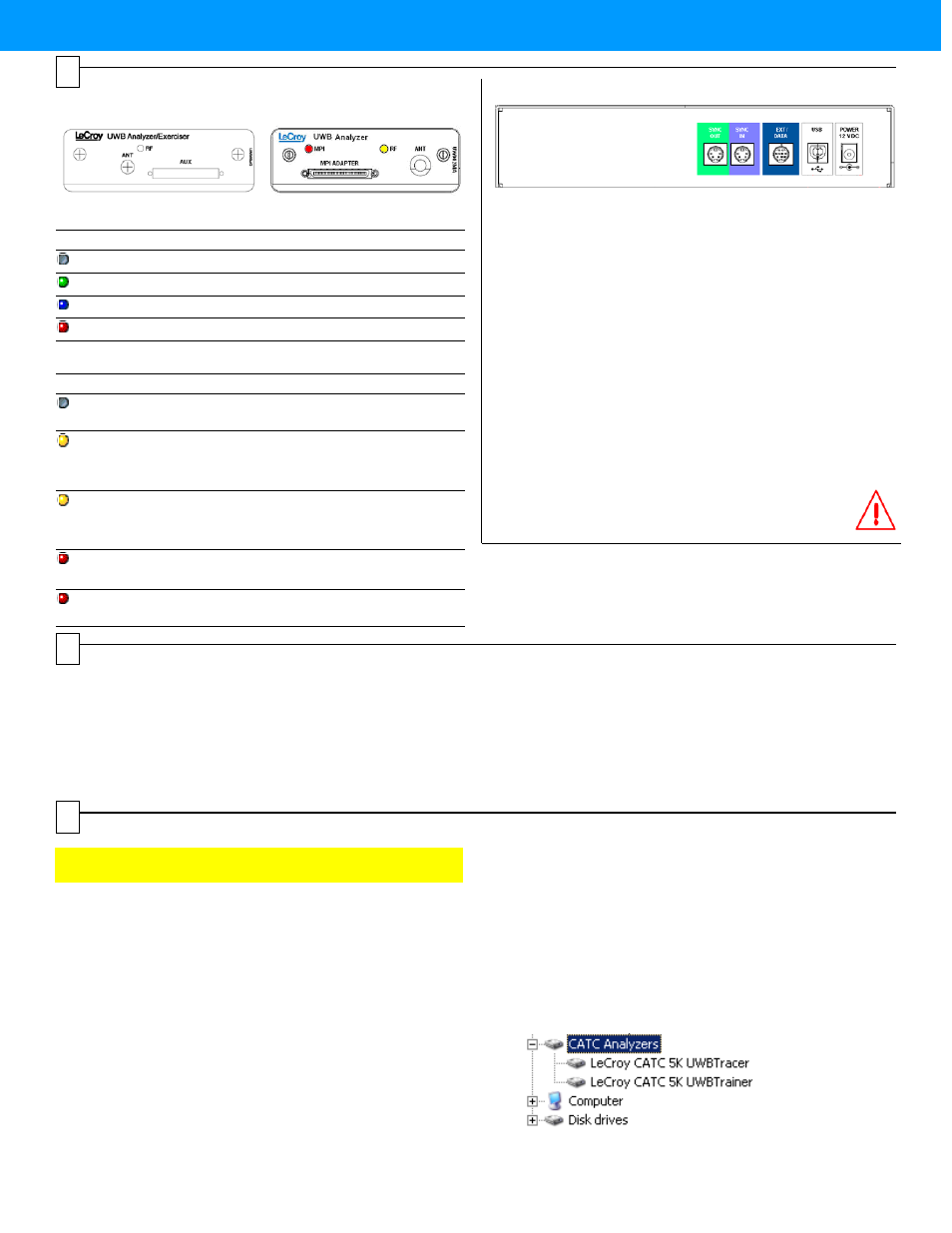
Rear Panel Description
SYNC IN / OUT
For synchronized multi-analyzer operation, the analyzers must be
connected in a daisy-chain topology to each other using the
Green/Purple cable.
EXT DATA
For attaching the TRIG-IN/TRIG-OUT BNC Y-cable to external
instruments
HOST
For connecting the analyzer through USB to the host machine
POWER 12VDC
For connecting the external power supply to the analyzer.
Note: There is no power switch on the analyzer.
Warning:
Do not open the CATC 5K enclosure. No
operator serviceable parts are inside. Refer
servicing to LeCroy.
MPI ADAPTER
Connector to MPI Adapter
ANT
SMA connector for antenna
LED
Description
No light
System is not powered on
Green Blink Slow
Initializing
Blue
System is operational
Red Blink Fast
System fault (contact Support)
LED
MPI Channel
RF Channel
No light
Does not detect
PCLK or PHY_ACTIVE
Does not detect wireless
frames
Yellow
Blink Fast
Trying to synchronize to
MPI traffic and waiting for
PCLK and PHY_ACTIVE
Trying to synchronize to
RF traffic and waiting for
wireless traffic
Yellow
Synchronized:
Capturing MPI traffic with
PHY_ACTIVE signal high
Synchronized:
Capturing wireless
frames
Red
Blink Slow
Recording
Pre-Trigger traffic
Recording
Pre-Trigger traffic
Red
Recording Post-Trigger
MPI traffic
Recording Post-Trigger
wireless traffic
Installing the Software
1.
If you have the Installation CD, put it in the CD drive on the host machine. The installation software should run automatically.
Select the Install software window, then select UWBTracer.
OR
If you install from the LeCroy web site, download the setup.exe file. Go to the directory where you saved the file and open the file to
run the installation program.
2.
Follow the on-screen instructions. The UWBTracer/Trainer software installs on the PC hard disk.
3
4
5