Front panel description, Lcd menus, Rear panel description – Teledyne LeCroy Summit T3-8 PCI Express Protocol Analyzer User Manual
Page 2: Interposers and probes, Installing the software
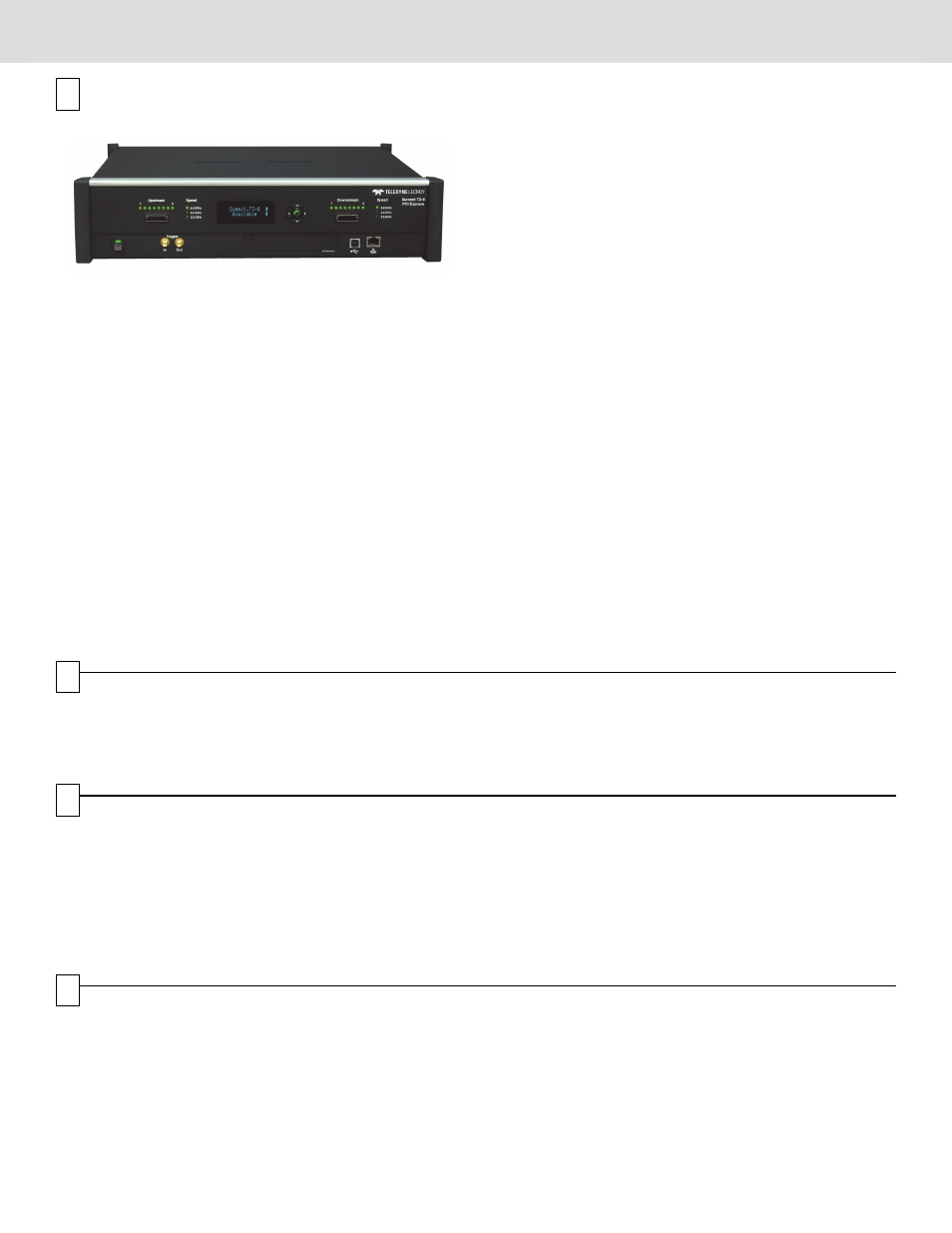
Front Panel Description
The Analyzer has the following features on the front:
[1] Power Switch (black): 1 = On and 0 = Off.
[2] UPSTREAM [7:0] connector: Connection to the probe for
the capture of upstream direction of the link.
[3] Speed LEDs: Indicate speed setting the analyzer is using for
each traffic direction.
[4] LCD Menus: Allows you to configure Summit T3-8 and view
status.
[5] Navigation Buttons: Navigate through the LCD menu.
[6] DOWNSTREAM [7:0] connector: Connection to the probe
for the capture of downstream direction of the link.
[7] Trigger IN and Out: Provide external trigger capabilities. You
can configure Summit T3-8 to trigger external equipment
using Trigger Out. You can use Trigger In to trigger the
Analyzer from another device.
[8] Expansion Slot: CATC Sync Expansion Card to use the
Teledyne LeCroy CrossSync application.
[9] USB Type B Host Machine Connector: To connect the
Analyzer to the host machine using a USB connection.
[10] Ethernet Port: 1 GIGE Connectivity allows connection to the
analyzer through an Ethernet network.
LCD Menus
The Summit T3-8 has a front LCD panel that displays the computer
name that is currently connected to the system, the unit serial
number, and the current network configuration. If no computer is
connected to the unit, the LCD panel displays Available.
The LCD panel also allows you to configure network settings for
the analyzer. Use the Up and Down keypad buttons to cycle
through the menu. Press the Center button to select.
Setup Static or Dynamic IP Mode
1.
Use the Up and Down buttons to navigate to the
Set IP Configuration menu.
2.
Press the Center button to start the setup.
3.
Use the Up and Down buttons to select Static or Dynamic
IP configuration.
4.
If you select the Static IP network configuration, you must
specify the IP address, Subnet mask, and Gateway. Use the
Up and Down buttons to navigate to the IP address, Subnet
mask, or Gateway.
5.
Press the Center button to enter edit mode.
6.
In edit mode, use the Left and Right buttons to move the
blinking cursor to any digit.
7.
Use the Up and Down buttons to modify the digit.
8.
After finishing modifications to the IP address, Subnet mask,
or Gateway, press the Center button to return to the menu.
9.
After you specify the IP address, Subnet mask, and Gateway,
use the Up and Down buttons to navigate to the Accept and
Reboot menu item. Press the Center button to apply the new
settings and restart the analyzer.
Note: To cancel your modifications, select the
Cancel Changes menu item.
Warning
Do not open the enclosure. No operator serviceable
parts are inside.
1
2
6
3
3
4
5
7
9 10
8
4
Rear Panel Description
The rear panel of the Analyzer has:
Wide-range AC Connector Module
•
Power socket
•
Enclosed 5.0 A 250 V fuse
Expansion Slot: Future use
Warning!
For continued protection against fire, replace fuse
only with the type and rating specified above.
5
Interposers and Probes
Gen3 Slot Interposer
The Gen3 Slot Interposer is designed for use with the Summit
T3-8 Analyzer and supports lane widths from x1 to x8 at data
rates of 2.5 GT/s (Gen1), 5.0 GT/s (Gen2), or 8.0 GT/s (Gen3). A
separate interposer is used for each lane width that you would like
to probe. Lane reducers should NOT be used with the Gen3 Slot
Interposer. For lane widths up to x8, one Analyzer Y-cable is
required.
Warning
Interposer has static-sensitive components.
Handle only at static-safe work stations.
Gen3 MidBus Probe
The Gen3 MidBus Probe is designed for use with the Summit
T3-8 Analyzer and supports lane widths from x1 to x8 at data
rates of 2.5 GT/s (Gen1), 5.0 GT/s (Gen2), or 8.0 GT/s (Gen3).
6
Installing the Software
The PETracer software operates all of Teledyne LeCroy’s PCI Express Protocol Analyzer and Exerciser products and and should be
installed on a Microsoft
®
Windows
®
-based host machine. You need to install the PETracer software on the host machine before attaching
the Analyzer to the system. The minimum requirements for the host machine are:
•
Microsoft Windows® XP, Windows 7 (x86, x64) Windows 8 (x86, x64), Windows Server 2003, Windows Server 2008 and Windows
Server 2012 R2
•
Processor with clock speed of 1 GHz or higher
•
2 GB of RAM
•
Hard drive with at least 250 MB of free space for software installation and additional space for storing recorded data
•
Display with at least 1024 x 768 resolution , with 16-bit color
•
USB 2.0 port
7