Connections – Teledyne LeCroy SFF-8639 to PCI Express 3.0 Adapter Quick Start User Manual
Page 2
3
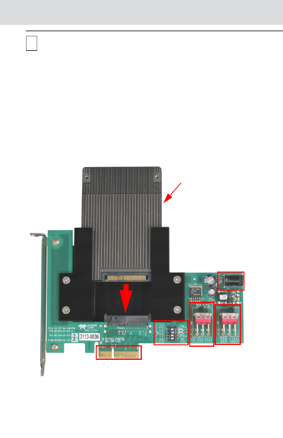
Connections
Perform to the following steps to connect the Adapter (see the image below):
1. Insert the SSF-8639 device under test (DUT) through the 2.5" bracket mak-
ing sure it connects properly in the bottom SSF-8639 connector.
2.
Make sure the power for the DUT is sourced correctly using switches SW2
and SW3. The factory default positions are SW1.1 OFF, SW1.2 ON, SW1.3
OFF, SW1.4 OFF, SW3 3.3V and SW2 12V HOST. See the tables below to
source the correct power for the DUT.
3.
Make sure only switch 2 from the DIP switch array SW1 is in the on position.
The PRSNT# pins configuration is X1 or X4 device is selected using SW1
according to the table.
4.
Plug the adapter with the device under test in any PCI Express slot.
5.
Connect the power supply to the external power jack (J3) if needed.
PCI Express (PCIe) Interface
(plugs into PCI Express slot)
Device Under Test
(DUT)
SW1
SW3
SW2
External power jack 12V
@ 3A minimum.
See section 4 for switch configurations.
- 6Zi Rackmount (12 pages)
- HDO Oscilloscope Rackmount (14 pages)
- LSIB-1 Host Interfaces (44 pages)
- OC1021 Oscilloscope Cart (9 pages)
- OC1024 Oscilloscope Cart (10 pages)
- OC910 Oscilloscope Cart (2 pages)
- TTL-AUX-OUT (1 page)
- WaveJet Rackmount (1 page)
- Zi Oscilloscope Rackmount (12 pages)
- USB2-GPIB (12 pages)
- WM8Zi-2X80GS (2 pages)
- WR6ZI-8CH-SYNCH (6 pages)
- Zi Oscilloscope Synchronization ProBus Module (Zi-8CH-SYNCH) (16 pages)
- LogicStudio (42 pages)
- WaveSurfer MXs-B Getting Started Manual (126 pages)
- WaveSurfer MXs-B Quick Reference Guide (16 pages)
- X-STREAM OSCILLOSCOPES Remote Control (305 pages)
- WS-GPIB (12 pages)
- PXA125 (219 pages)
- PXD Series (42 pages)
- PXD222 (38 pages)
- Oscilloscope System Recovery (8 pages)
- LabMaster 9Zi-A (264 pages)
- LabMaster 10Zi Rackmount (8 pages)
- LabMaster 10Zi Getting Started Manual (236 pages)
- LabMaster 10Zi Operators Manual (198 pages)
- WaveAce 1000_2000 (108 pages)
- WaveAce 1000_2000 Remote Control (92 pages)
- WaveRunner Xi-A Quick Reference Guide (16 pages)
- WaveRunner XI SERIES Operator’s Manual (233 pages)
- WaveMaster Automation Command (667 pages)
- WaveMaster 8 Zi_Zi-A (190 pages)
- WaveMaster 8000A (46 pages)
- WavePro 7 Zi_Zi-A (188 pages)
- WaveExpert series Automation Manual (285 pages)
- WaveExpert 9000_NRO9000_SDA100G Getting Started Manual (50 pages)
- WaveExpert 100H Operators Manual (348 pages)
- WaveRunner Automation Command (460 pages)
- WaveRunner Xi-A Getting Started Manual (128 pages)
- WaveRunner 6 Zi and 12-Bit HRO Getting Started Manual (198 pages)
- WaveRunner 6 Zi Quick Reference Guide (20 pages)
- WaveRunner 6 Zi-ExtRef-IN_OUT (2 pages)
- WaveSurfer Automation Command (226 pages)
- HDO 4000 Getting Started Guide (48 pages)
- HDO Removable Hard Drive (2 pages)