Teledyne LeCroy PCI Express 2.0 Multi-Lead Probe for Summit T24 User Manual
Gen2 multi-lead probe user manual for summit™ t24
Introduction
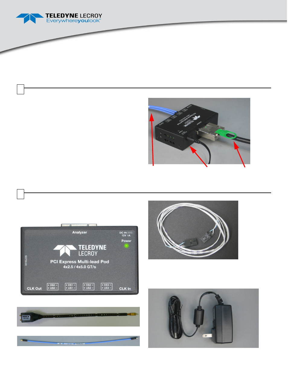
The Teledyne LeCroy Gen2 Multi-Lead Probe is designed to tap
and test inter-chip signaling on a PCI Express board. Figure 1
shows the Gen2 Multi-Lead Probe Pod and attached cables.
A Gen2 Multi-Lead Probe has a Gen2 Multi-Lead POD (POD in
Figure 1), High Bandwidth coax cables (C), and a
Differential Flex Tip Assembly for easy connection (for photo, see
Section 2, Components).
Figure 1 also shows an iPass x4 to x8 straight cable (S), which
connects to a Summit T24™ Analyzer.
Figure 1. Teledyne LeCroy Gen2 Multi-Lead Probe Pod and
Components (Ref clock cable not shown)
C
S
POD
Gen2 Multi-Lead Probe
User Manual for Summit™ T24
Before Starting
Use this document for quick installation and setup. If you
experience problems or need more information, see the
PETracer/Trainer User Manual on the Installation CD or at the
Teledyne LeCroy web site. For details about the latest software
version, see the Readme.html file on the Installation CD.
Components
The Teledyne LeCroy Gen2 Multi-Lead Probe has the
following components:
•
Gen2 Multi-Lead POD (POD in Figure 1)
•
Gen2 Multi-Lead Probe Differential Flex Tip
•
High Bandwidth Coax Cable Assembly (C in Figure 1)
•
Clocking Cable Assembly
•
Retention Modules, which are plastic guides for
connecting cables at the DUT (not shown here; see
description in Section 3, Hardware Installation).
•
Power Supply shown below:
1
2