Installing the rack mount brackets 3 – Teledyne LeCroy 1U Height Systems Rack Mount User Manual
Page 3
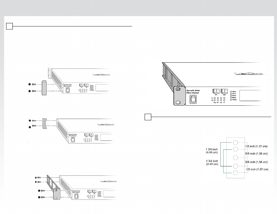
Take the following steps to attach the two brackets to the system chassis:
Installing the Rack Mount Brackets
3
Step 1:
Place the system chassis on a sturdy surface.
Step 2:
Using the 9/64” Allen Key provided, unscrew the two screws that
attach one of the front rubber bumpers to the system enclosure (see
illustration below). Keep these screws as they will be used to attach
the new rack mount brackets (see Steps 6-7).
Step 3:
Repeat this procedure to remove the other front rubber bumper.
Step 4:
Remove the two screws that attach one of the rear rubber bumpers to
the system enclosure (see illustration below):
Note: The SierraFC M164
is used as an example in
these illustrations. The steps
are identical for other 1U systems.
Step 5:
Repeat this procedure to remove the other rear rubber bumper.
Step 6:
Attach one of the brackets (shown below) to the left side of the system
chassis using the 9/64” Allen Key provided and four of the screws that
previously attached the rubber bumpers (these are the screws that
were removed in Steps 2-5). See illustration below.
Step 7:
Attach the other bracket to the right side of the system chassis (using
the remaining four screws that were removed).
Note:
Store the four rubber feet removed from the system in case you would
like to return the system to the original configuration at a later time.
Planning the Installation
4
Planning the Installation
Installing the system chassis in a rack mount enclosure requires some planning for
issues such as location, spacing, airflow and power supply. These issues are
reviewed below.
Location
Most rack mounts conform to the
Most rack mounts conform to the
EIA 310-D (RETMA) standard,
which provides mounting holes on
two vertical support rails which are
separated by 19” (480 mm). This
standard provides separation of the
spacing holes in increments of both
1/2” (12.7 mm) and 5/8” (15.8 mm),
/
(
) a d 5/8 ( 5 8
),
which allows for various multiples
of these spacing distances (such
as 1.75” [44.5 mm] which is
obtained by the separation of two 5/8” gaps and one 1/2” gap). See the diagram
on the right. The rack mount brackets supplied use 1.75” spacing.