5 front panel led and switch board – Asus AP2400R-E1 User Manual
Page 50
Chapter 2: Hardware setup
2-36
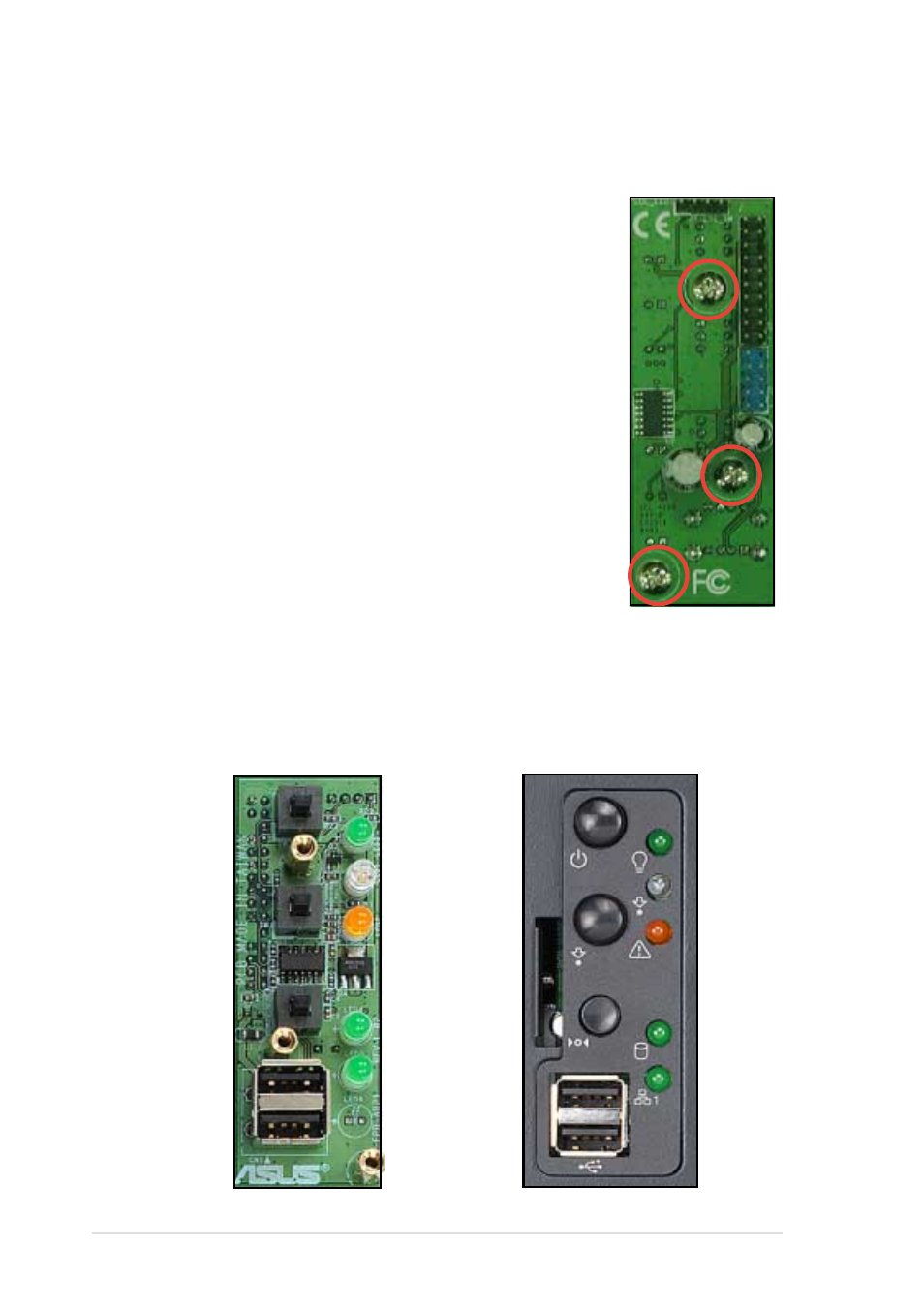
2.7.5 Front panel LED and switch board
To uninstall the front panel and swtich board:
1. Disconnect all cables connected to the rear of the
board.
2. Remove the three screws the secure the board to
the chassis.
3. Carefully remove the board out of the chassis.
When removed, the LED and switch board appears as shown. The LEDs
and switches on the board correspond to the LEDs and buttons on the
system front panel.
Front side
Front panel LEDs and buttons
Rear side
See also other documents in the category Asus Computers:
- CG8565 (410 pages)
- CG8565 (246 pages)
- CS5111 (26 pages)
- CS5120 (1 page)
- ET1611PUK (38 pages)
- S2-P8H61E (80 pages)
- P2-PH1 (80 pages)
- P1-P5945G (80 pages)
- P2-P5945GCX (90 pages)
- CG8270 (536 pages)
- CG8270 (72 pages)
- CG8270 (76 pages)
- CG8270 (534 pages)
- CG8270 (362 pages)
- CG8270 (218 pages)
- P3-P5G31 (100 pages)
- P3-PH4 (80 pages)
- P2-M2A690G (80 pages)
- P2-M2A690G (8 pages)
- P4-P5N9300 (82 pages)
- P4-P5N9300 (1 page)
- P1-P5945GC (92 pages)
- P2-P5945GC (92 pages)
- P3-P5G33 (98 pages)
- T3-P5945GC (80 pages)
- T3-P5945GCX (80 pages)
- P2-M2A690G (94 pages)
- T3-PH1 (80 pages)
- T3-PH1 (82 pages)
- T5-P5G41E (76 pages)
- T5-P5G41E (82 pages)
- S1-AT5NM10E (68 pages)
- P6-P7H55E (67 pages)
- ES5000 (174 pages)
- T4-P5G43 (104 pages)
- T-P5G31 (92 pages)
- BT6130 (60 pages)
- BT6130 (54 pages)
- BT6130 (2 pages)
- CG8265 (350 pages)
- CG8265 (210 pages)
- CM1740 (70 pages)
- CM1740 (198 pages)
- CM1740 (330 pages)
- P6-M4A3000E (59 pages)