2 installing a cpu, Cpu onboard led, Chapter 2: hardware setup 2-10 – Asus AP2400R-E1 User Manual
Page 24
Chapter 2: Hardware setup
2-10
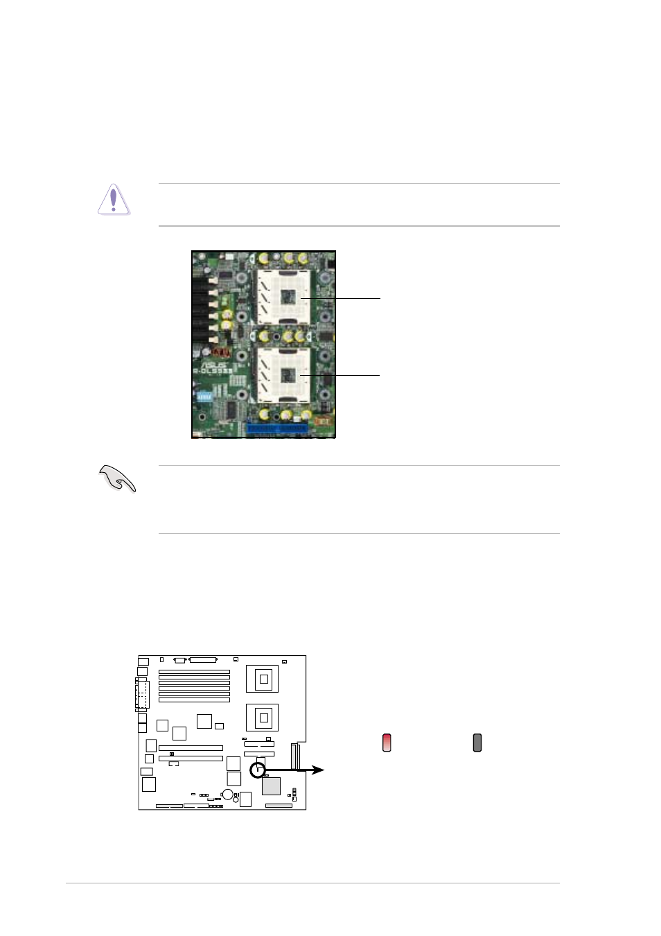
2.2.2 Installing a CPU
Note in the illustration that the CPU has a gold triangular mark on one
corner. This mark indicates the processor Pin 1 that should match a
specific corner of the CPU socket.
Incorrect installation of the CPU into the socket may bend the pins and
severely damage the CPU!
1. The motherboard supports either one or two CPUs. If you are
installing only one CPU, you MUST install it in CPU socket 1.
2. If you are installing two CPUs, install in the CPU socket 2 first.
CPU onboard LED
This warning LED (LED1) lights up if you installed two CPUs of different
type/voltage. You must install identical CPUs on this motherboard.
PR-DLS533
PR-DLS533 Onboard LED
LED1
ON
CPU Type/Voltage
not identical
OFF
CPU Type/Voltage
identical
CPU Socket 1
(outer socket)
CPU Socket 2
(inner socket)
- CG8565 (410 pages)
- CG8565 (246 pages)
- CS5111 (26 pages)
- CS5120 (1 page)
- ET1611PUK (38 pages)
- S2-P8H61E (80 pages)
- P2-P5945GCX (90 pages)
- P2-PH1 (80 pages)
- P1-P5945G (80 pages)
- CG8270 (362 pages)
- CG8270 (218 pages)
- CG8270 (536 pages)
- CG8270 (72 pages)
- CG8270 (76 pages)
- CG8270 (534 pages)
- P3-P5G31 (100 pages)
- P3-PH4 (80 pages)
- P2-M2A690G (80 pages)
- P2-M2A690G (8 pages)
- P4-P5N9300 (82 pages)
- P4-P5N9300 (1 page)
- P1-P5945GC (92 pages)
- P2-P5945GC (92 pages)
- P3-P5G33 (98 pages)
- T3-P5945GC (80 pages)
- T3-P5945GCX (80 pages)
- P2-M2A690G (94 pages)
- T3-PH1 (82 pages)
- T3-PH1 (80 pages)
- T5-P5G41E (76 pages)
- T5-P5G41E (82 pages)
- S1-AT5NM10E (68 pages)
- P6-P7H55E (67 pages)
- ES5000 (174 pages)
- T4-P5G43 (104 pages)
- T-P5G31 (92 pages)
- BT6130 (60 pages)
- BT6130 (54 pages)
- BT6130 (2 pages)
- CG8265 (210 pages)
- CG8265 (350 pages)
- CM1740 (330 pages)
- CM1740 (70 pages)
- CM1740 (198 pages)
- P6-M4A3000E (59 pages)