Winch installation – Superwinch H14P PRO - 6,020 kgs Manual Clutch (Long Drum) complies with EN14492-1 User Manual
Page 5
Owners Manual 5-201-003 Issue 1
5
Page
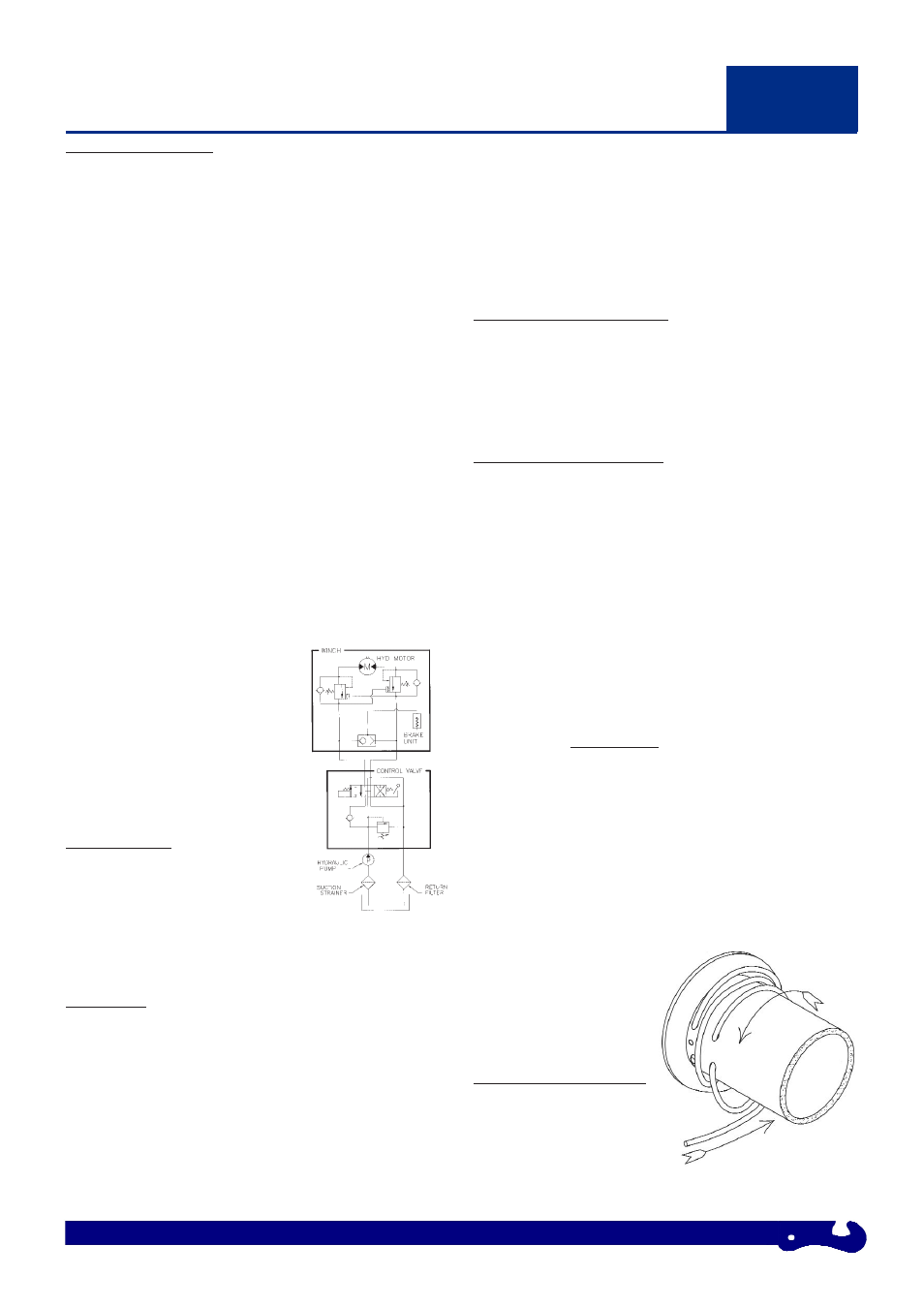
HYDRAULIC SYSTEM
System Type: Open system with filtered return line
Relief Valve: IMPORTANT - Set at winch operating pressure
Pump: With a maximum oil supply of 60 l/min at top motor rpm.
The pump must be capable of delivering a pressure of 170 bar.
Reservoir:
Must be fitted with an oil filter device comprising
strainer and air filter and a dip stick. The capacity of the tank should
be at least 60 litres (16 U.S. gal). Note: Do not fill the tank to the top,
since there must be space for expansion in the tank. Suitable
hydraulic oil is Castrol CRML or equivalent (150 LHM 32 - 68).
Typical viscosity rating of 150 - 175 cSt at 100°c.
Hoses: Should have the minimum following dimensions:
Pump inlet line: 32 - 38mm (1 1/4” - 1 1/2”)
Nominal Bore (N.B.)
(reservoir to pump)
Return line: 25mm (1”) N.B.
(control valve to reservoir)
Pressure hoses: 13mm (1/2”) N.B.
(control valve to load control valve)
Pressure and flow loss is increased as hose length increases and/or
bore size decreases. Pressure and return lines in excess of 3.5 meters
should be compensated with an increase in nominal bore size.
Control Valve 4 - way, 3 - position with spring centred, open centre
(ports A & B open when in centre position) and built in relief valve.
The relief valve must be set to the winch operating pressure. The
valve should be mounted as close to the winch as possible
Load Control Valve: A dual overcentre
valve is fitted to the winch to give
smoothly controlled winch out when
under load and to provide full dynamic
braking.
Oil Suction Strainer Rating:
Approximately 250 microns
Return Line Filter Rating:
10 - 40 microns
INSTALLATION
In all installation work on a hydraulic
system, cleanliness and accuracy are
essential so that the hydraulic system
functions properly.
As a general rule:
Bigger Nominal Bore Hose = Better Winch Performance
MOUNTING
The diagrams on page 6 show the mounting dimensions for the
Superwinch H12P and H14P.
The side and feet mounting hole positions are designed to allow the
winch to be interchangeable with the most popular 12000 - 14000 lbs
units currently available. If a Superwinch mounting plate is not used,
the surface must be flat within 0.5 mm and sufficiently stiff to
prevent flexing. A minimum of 6.0 mm thick steel plate should be
used. The thicker the plate, the better the alignment between motor
mounting, drum and gearbox housing.
It is important that the winch is mounted securely so that the motor
mounting, drum and gearbox housing are accurately aligned. Be sure
the winch will not move under load, otherwise you may cause
misalignment in the winch, causing the drum to bind up.
The tie bars supplied with the winch must remain attached when the
winch is foot mounted. Angle mounting is possible and
recommended for maximum flexibility in mounting. These mounts
allow the winch to be low-mounted.
WIRE ROPE SPECIFICATION
The rope must be of good quality, have a steel core and meet the
specification detailed on the certificate of conformity.
Avoid pulling a load at more than a 15 degree angle in relation to
the winch. This will reduce wear and tear on the winch and the
cable.
WIRE ROPE INSTALLATION
1. Remove Rope Drum safety guard.
2. Unwind the cable by rolling it out along the ground
with the tapered end nearest to the winch. NEVER wind the cable
straight onto the drum from a coil.
3. Raise the cable tensioner away from the rope drum (if supplied
as part of your kit), and lock in position through the corresponding
holes in the tensioner frame and bracket using a suitable pin or bolt.
4. Rotate the rope drum under power until the rope fixing holes run
vertically at the front of the winch.
5. Pass the rope end through the roller fairlead, under the drum and
back over the top of the drum to pass through the rope hole furthest
way from the drum flange. Keep feeding the rope through to wrap
around the drum FOUR TIMES and into the rope fixing hole
nearest the drum flange.
6. Tighten the retaining screw ensuring that the rope end is flush
with the exit of the hole and not protruding.
7. Feed back any excess slack to tighten the four wraps neatly on
the drum.
8. Remove the locking pin from the cable tensioner to allow the
rollers to rest on the rope. Note: This assembly is under tension.
Special care should be taken to avoid trapping fingers, clothing etc.
9. Apply moderate tension to
the rope. Take care to ensure
the layers are neatly wrapped,
as this will minimise damage
to the lower layers of rope
when a load is applied.
PULLING OUT THE ROPE
Dis-engage the freespool. With
a pair of gloves on, pull out the
rope and secure to anchor or
load. Re-engage the freespool.
Note: Two wraps illustrated for clarity.
03
WINCH INSTALLATION
WITH LOAD CONTROL
- H14P PRO - 6,020 kgs Manual Clutch (Standard Drum) complies with EN14492-1 H14P PRO- 6,020 kgs Pneumatic Clutch (Standard Drum) complies with EN14492-1 H14P PRO - 6,020 kgs Pneumatic Clutch (Long Drum) complies with EN14492-1 H12P PRO - 5,100 kgs Manual Clutch (Long Drum) complies with EN14492-1 H12P PRO - 5,100 kgs Manual Clutch (Standard Drum) complies with EN14492-1 H12P PRO - 5,100 kgs Pneumatic Clutch (Long Drum) complies with EN14492-1 H12P PRO - 5,100 kgs Pneumatic Clutch (Standard Drum) complies with EN14492-1