Connections of initiating devices and accessories – LiftMaster LM21AFCB Advance Fire Control Release Device User Manual
Page 7
7
CONNECTIONS OF INITIATING DEVICES AND
ACCESSORIES
A maximum of 4 smoke detectors may be installed with this
device. Refer to NFPA 72 and NFPA 80 for instructions
concerning proper placement and detection coverage. End-of-line
devices must be installed for supervision of electrical power to
4-wire smoke detector. When using 4-wire smoke detectors with
this device, electrical supervision must be provided by means of a
UL/ULC listed end-of-line relay.
NOTE: For low voltage wiring #18 AWG is recommended.
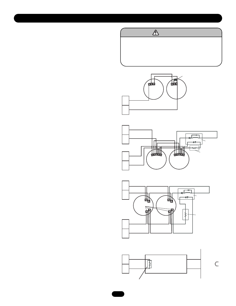
Normally Open “2-Wire,” Class B Style A 12Vdc Initiating
Devices
1. Connect wiring from N/O initiating device loop to terminals 2
and 3.
2. Place the supervisory resistor (LMEOLRES-2-2) across the
terminals of the last initiating device. Observe proper polarity,
2 (+), 3 (-) (Figure 3).
OR
Normally open “4-Wire,” Class B Style A Initiating Devices
1. Connect wiring from N/O 4-Wire initiating device loop to
terminals 2 and 3. (Do not share alarm loop with other alarm
circuits.)
2. Place the supervisory resistor (LMEOLRES-2-2) as illustrated
in figure 4 or 5. (Do not share alarm loop with other alarm
circuits.)
3. Auxiliary power (+24Vdc) for smoke detectors may be
obtained from terminals 1 (+) and 4 (-) for +24Vdc. There is a
4 detector maximum, and an end-of-line relay device must be
used (Figures 4 & 5).
NOTE: End-of-line devices must be installed adjacent and after
the last initiating device. Initiating device loops are supervised
and cannot be direct series or paralleled between multiple release
devices or shared with other alarm equipment. For proper wiring
configurations from multiple smoke detectors or signaling for
simultaneous closure on multiple doors, call technical support,
1-888-528-7870. Incorrect wiring between devices may cause
damage to the release control circuit and void warranty.
4. In lieu of smoke detectors, the release device may be put into
alarm by the fire alarm control panel. Most commonly, a relay
module is used as an interface between the fire alarm control
panel and the release device. The relay module must provide
Form C dry contacts for connection to the appropriate
terminals on the release device (Figure 6).
NOTE: When choosing a relay module to activate the release
device in an alarm condition, always select one that provides
Form C dry contact relays. Do not use any relay module
providing or passing any (control) voltage through the contacts
into the release device. The passage of voltage through such a
relay module into the release device will cause problems with the
operation of the device and may damage the device's terminals
and/or circuit board.
W I R I N G
To prevent possible SERIOUS INJURY or DEATH:
• End-of-line devices MUST be installed for supervision of
electrical power to 4-wire smoke detector.
• DO NOT install this device on a motorized door without an
electric safety edge.
ATTENTION
AVERTISSEMENT
AVERTISSEMENT
AVERTISSEMENT
WARNING
CAUTION
WARNING
WARNING
WARNING
PRECAUCIÓN
ADVERTENCIA
ADVERTENCIA
ADVERTENCIA
Figure 3
– IN/OUT
+ OUT
+ IN
– IN/OUT
+ OUT
+ IN
2
3
2
3
1
4
COM
NO
– IN/OUT
+ OUT
+ IN
COM
NO
– IN/OUT
+ OUT
+ IN
(–)
(+)
(–)
(+)
2
3
1
4
2
3
–
+
Figure 5
Figure 6
2.2k Ohm @ 1/2 watt
Supervisory Resistor
(LMEOLRES-2-2)
NOTE: Follow this method of
attachment when using LM2W-B,
LM2WT-B, other 2-wire smoke
detector. See last page for
approved devices.
On Circuit
Board
NOTE: Follow this method
of attachment when using
LM4W-B or LM4WT-B.
2.2k Ohm @ 1/2 watt
Supervisory Resistor
(LMEOLRES-2-2)
LMEOLR1224
12/24 Vdc
EOL Relay
NOTE: Follow this
method of attachment
when using LM1424.
2.2k Ohm @ 1/2 watt
Supervisory Resistor
(LMEOLRES-2-2)
LMEOLR1224
12/24 Vdc
EOL Relay
Alarm
Contacts
Style A
(N/O)
Relay Module
Normally Open
Common
2.2k Ohm @ 1/2 watt
Supervisory Resistor
(LMEOLRES-2-2)
Red
Black
Fire Alarm
Control
Panel
Figure 4