M a i n t e n a n c e, Enclosure mounted leds status indicators – LiftMaster LM21AFCB Advance Fire Control Release Device User Manual
Page 14
M A I N T E N A N C E
To avoid SERIOUS PERSONAL INJURY or DEATH from
electrocution, disconnect ALL electric and battery power
BEFORE performing ANY maintenance.
ATTENTION
AVERTISSEMENT
AVERTISSEMENT
AVERTISSEMENT
WARNING
CAUTION
WARNING
WARNING
WARNING
PRECAUCIÓN
ADVERTENCIA
ADVERTENCIA
ADVERTENCIA
MAINTENANCE
The release device has no scheduled maintenance requirements.
The device has been designed and tested for use in dry, indoor
locations. Testing of the device at least once every 90 days is
recommended, but test intervals shall ultimately be subject to
criteria established by the Authority Having Jurisdiction (AHJ).
FUSE REPLACEMENT PROCEDURE AND REPAIR PARTS
Two serviceable fuses, both 2 Amp, 2AG, slo-blo fuses, are
required for proper operation and protection of the power supply
circuit board. The fuse present at position F1 limits the amount of
current coming into and going from the battery. The fuse present
at position F2 limits amount of current into power supply board.
The device is shipped with the fuses installed and replacement
fuses (2) are provided in a separate parts bag.
For replacement parts, refer to Accessories and Replacement
Parts page.
BATTERY MAINTENANCE/TESTING
No maintenance or testing is required for the battery. An audible
warning tone, generated by the trouble annunciator, will sound
when the battery is approaching the minimum operating
threshold. This indicates the need to replace the battery. Replace
the batteries every 2 years.
For replacement parts, refer to Accessories and Replacement
Parts page.
BATTERY DISPOSAL
Spent batteries must be treated as hazardous waste and disposed
of in accordance with State, Local and Federal Regulations.
Battery
Green
(Fig. 13)
If the Green LED is lit, then the battery is connected
properly and charged above the minimum acceptable
level.
If the LED does not light, check that the leads are
connected to the battery as shown on the wiring diagram
in this manual. Check Battery Fuse, F1 (Fig. 12).
Disable
Yellow
(Fig. 13)
If the Yellow LED is lit, the releasing device will attempt to
close through the operator and not perform a mechanical
release door closure in alarm. It should light if the
operator control voltage is connected or the auxiliary close
limit is active
Connect operator control voltage connections to terminals
11, 12 and auxiliary close limit connections to terminals
13, 14.
Power
Red
(Fig. 13)
If the Red LED is lit, then the line power is connected and
switched “on.”
If the LED does not light when power is applied, check
that power is connected as described in the installation
manual electrical connections.Check 24Vac Fuse,
F2, (Fig. 12).
ENCLOSURE MOUNTED LEDS STATUS INDICATORS
14
LED Label LED Color
Description
Action Required
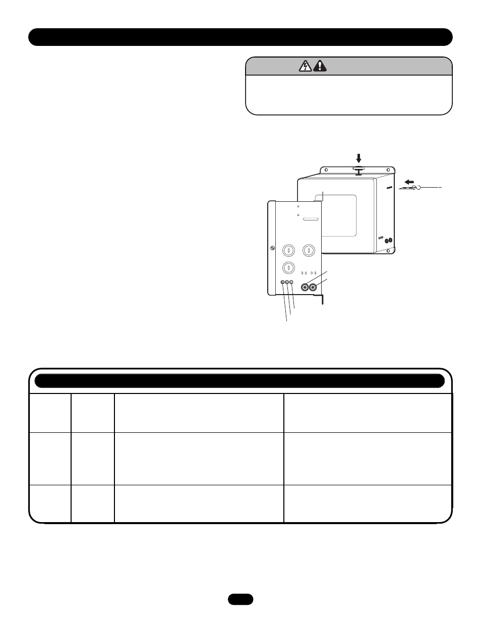
Front of Release Device
End Link
Mechanical
Reset Plunger
Test Button
Electronic
Reset Button
Side of
Release Device
Yellow LED (Close Door Detection/Release Disabled)
Red LED (Line Power Present)
Green LED (Battery Backup Power Present)
Figure 13