T r o u b l e s h o o t i n g, Diagnostic leds – LiftMaster LM21AFCB Advance Fire Control Release Device User Manual
Page 13
Battery
Present
Green
(Fig. 13)
If lit, batteries have been installed correctly and are
charging or have been fully charged.
If the LED does not come back on after installing the
batteries, check battery connections are as illustrated.
Open Limit
Green
(Fig. 11)
If lit, the device senses a triggered normally open limit
switch.
If door is on the Open limit, input is connected properly. If
door is not on the Open limit, check that auxiliary limit
connections are made as illustrated.
Close Limit
Green
(Fig. 11)
If lit, the device senses a triggered normally close limit
switch.
If door is on the Close limit, input is connected properly. If
door is not on the Close limit, check that auxiliary limit
connections are made as illustrated.
Mechanical
Release
Disabled
Yellow
(Fig. 13)
If lit, the device is in a state where it will not release the
door.
This is caused by being in close limit or by sensing an
electric door operator. Check limit switch connections and
motor operator control voltage connections.
Annunciator
Open
Yellow
(Fig. 11)
If lit, 2.2k Ohm resistor is not installed on the annunciator
circuit. Note that LED lights when system is in alarm condition.
Check that the annunciator is installed as described in
Wiring Instructions.
Detector
Open
Yellow
(Fig. 11)
If lit, 2.2k Ohm resistor is not installed on the smoke
detector circuit.
Check that a 2.2k Ohm resistor is connected in the circuit
as illustrated.
Ground
Fault
Yellow
(Fig. 12)
If lit, a short to earth ground exists.
Check that release device and all ancillary devices/loops
(detectors, annunciators, etc.) are grounded properly.
Annunciator
Short
Red
(Fig. 11)
If lit, the annunciator circuit is short-circuited.
Check that the annunciator is installed as described in
Wiring Instructions.
Line Power
Present
Red
(Fig. 13)
If lit, the line power is connected and switched “on.”
If the LED does not light when power is applied, check
that the power is connected to L1 and L2 as described in
Wiring Instructions.
Detector
Short
Red
(Fig. 11)
If lit, the smoke detector circuit is short-circuited.
Check that the smoke detectors are connected in the
circuit as illustrated. Press the “Reset” button to reset the
detectors.
13
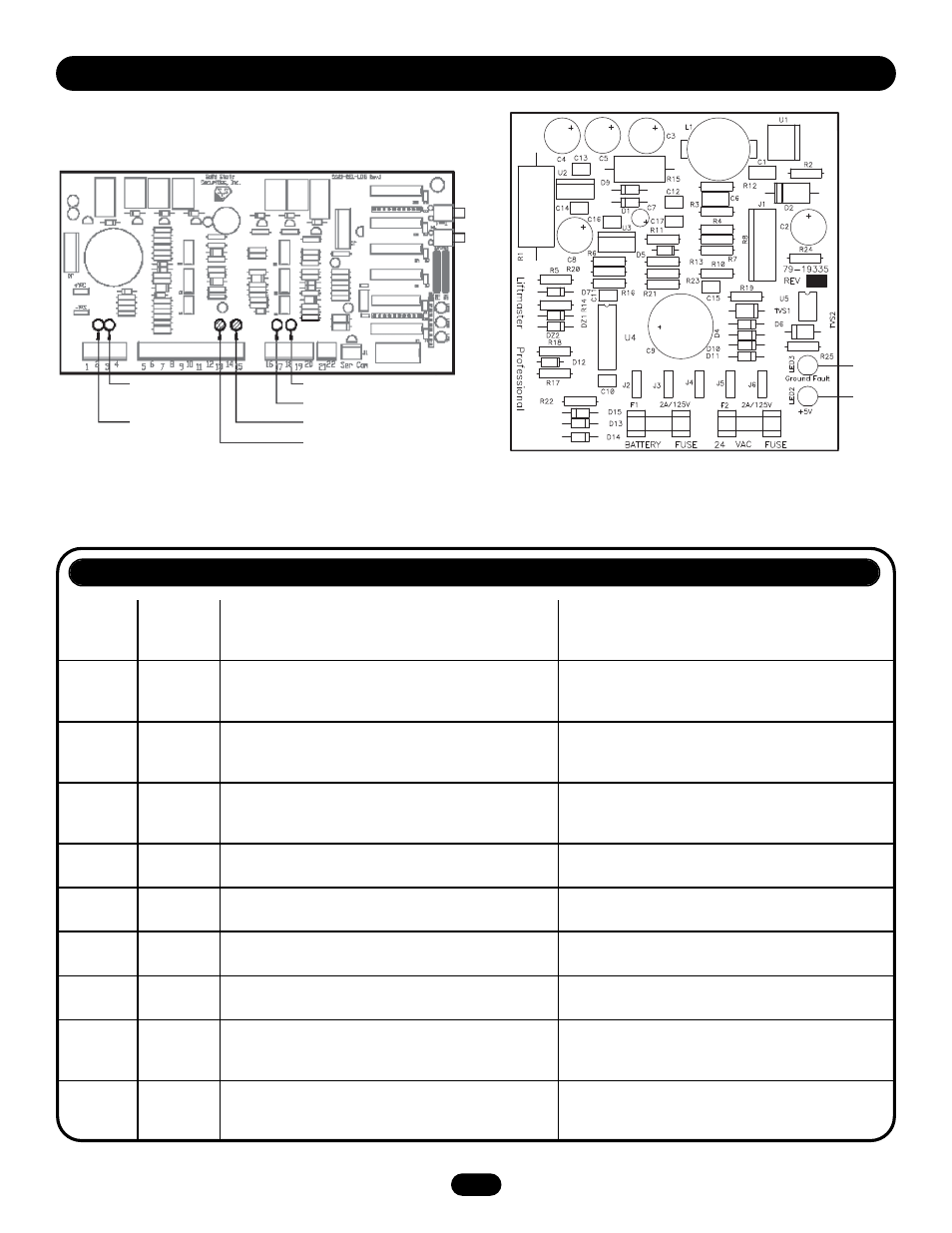
T R O U B L E S H O O T I N G
DIAGNOSTIC LEDS
LED
LED Color
Description
Action Required
Figure 11 - Logic Board LED Descriptions
Figure 12 - Power Supply Board LED Descriptions
Close Limit (Green)
Ground Fault
(Yellow)
Power
(Red)
Detector Open
(Yellow)
Open Limit (Green)
Annunciator Short (Red)
Detector Short
(Red)
Annunciator Open (Yellow)