Signal and optional switch connections, Enable/disable switch – LEESON FHP Series Chassis Mount Variable Speed Drives User Manual
Page 43
33
Installation
Signal and Optional Switch Connections
All signal and switch connections are made at TB501.
Terminal block orientation and terminal names are identical
for all FHP series drives. Use 20 - 24 AWG wire for speed
adjust potentiometer and switch connections.
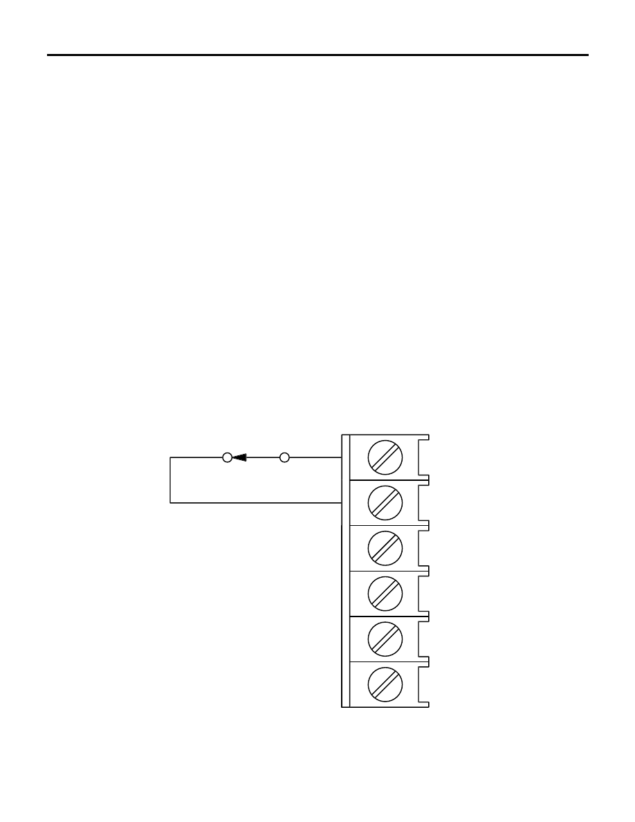
ENABLE/DISABLE switch
Connect a single-pole, single-throw ENABLE/DISABLE
switch between the ENABLE (E2) and COMMON (E1)
terminals as shown. Open the switch to disable the drive
and coast to a stop. Close the switch to accelerate to set
speed at a rate controlled by the ACCEL trimpot.
E2
E1 (COMMON)
S1
S2
D
S3
ENABLE/DISABLE SWITCH
OPEN TO DISABLE
TB501
Figure 20. Enable / Disable Switch connections to TB501