14 installation, J501, L1 l 2 – LEESON FHP Series Chassis Mount Variable Speed Drives User Manual
Page 24: Installation complete
14
Installation
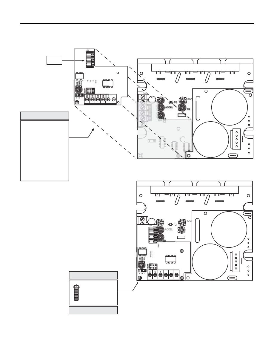
SECURE THE
PCM ADDER
BOARD WITH
THE 6-32 x 1 5/16"
PHILLIPS SCREW.
S T E P # 8
V
U
W
J501
C501
C502
TH501
L
1
L
2
1
1
5
V
230
V
DECEL
D
JMP501:INPUT R
A
1:0-5V
D
2:0-10
V
3
:4
-20M
J
MP
502
:INP
U
T TYP
E
TB5
01
2-3:
C
URREN
T
1-2:V
O
LTA
GE
POSITION THE PCM
ADDER BOARD OVER
THE BOTTOM BOARD
AS SHOWN.
NOTE: First align the
bottom holes of J501 (on
the PCM adder board) with
the 6 pin header installed
on the bottom board. The
PCM adder board will
snap into place at J501
and the two standoffs.
S T E P # 7
TB501
V
U
W
J501
C501
C502
TH501
L
1
L
2
1
1
5
V
230
V
TQ
DECEL
S2
S3
D
0
1:INP
U
T RAN
GE
1:0-5VD
C
2:0
1
0VDC
JMP5
02
:INPUT TYP
E
TB5
01
2-3:
C
URREN
T
1-2:V
O
LTA
GE
J501
INSTALLATION COMPLETE.
C510
IC502
J501
JMP501