Wiring instructions, Save these instructions, Danger – King Electric ESP Electronic Programmable User Manual
Page 3: Electric shock or fire hazard
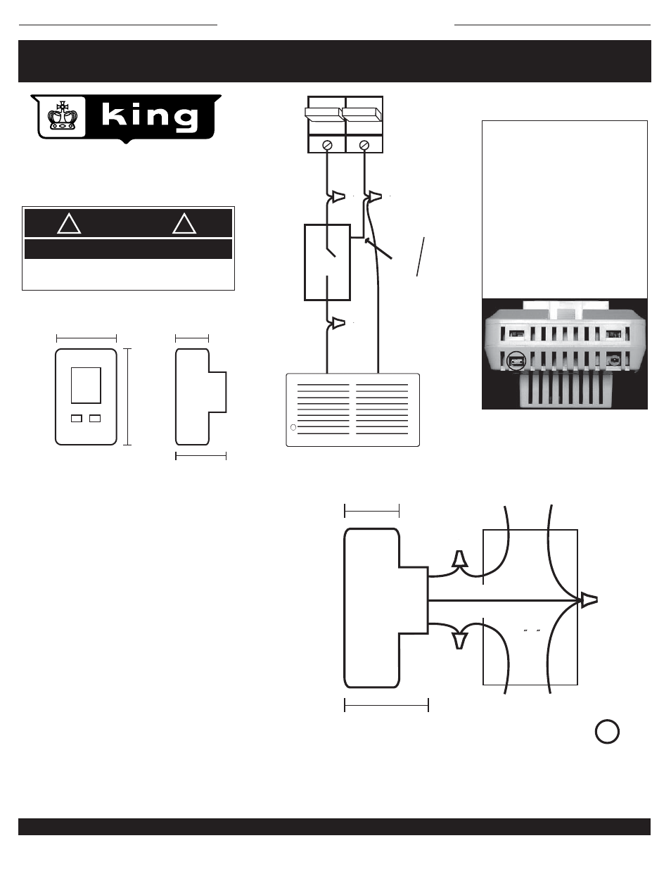
WIRING INSTRUCTIONS
DANGER
!
!
ELECTRIC SHOCK OR FIRE HAZARD
READ ALL WIRE SIZING, VOLTAGE REQUIREMENTS AND SAFETY
DATA TO AVOID PROPERTY DAMAGE AND PERSONAL INJURY
4 7/8"
3 1/8"
1 1/4"
2"
1. To wire the thermostat determine which pair of wires are coming
from the breaker panel and which pair lead to the heater.
2. With wire nuts attach the blue wire (white wire on 120 Volt model
ESP120) into the pair of white wires in the junction box.
3. Take a black lead from the circuit breaker panel and attach it to
the black lead on the thermostat. This will provide power to the
thermostat, LCD display, backlighting and heater relay.
4. Take the black lead that goes to the heater and attach it to the
red lead on the thermostat. This will provide power to the heater
when the thermostat calls for heat.
5. Remove cover of thermostat by holding back of thermostat and,
with a finger and thumb on the top and bottom of the thermostat,
pull cover towards you evenly to remove cover and expose
mounting holes and buttons.
6. Push the wires carefully into the junction box making sure no
wires are pinched or will get in the way of the screws mounting the
thermostat. Now attach the thermostat to the wallbox with the #6-
32 screws provided.
7. Hold thermostat into wallbox and place screws in top and bottom
mounting hole and attach to wallbox.
8. Turn on power and test by increasing set point to higher than
room temperature by tapping the up button. There will be up to a 3
minute delay in turning on. The indicator light will turn on and you
will here a small click and at the same time and the heater should
be on. Turn the thermostat down by tapping on the down arrow.
BLACK
BLACK
BLACK
WHITE
WHITE
LINE 2
CIRCUIT
BREAKER
LINE 1
THERMOST
AT
240V
BLUE
120V
WHITE
RED
HEATER - UP TO 5280 WATTS
1 1/4"
BLACK
BLACK
2 X4
JUNCTION
BOX
RED
WHITE
BLACK
TO HEATER
POWER IN
(Line)
(Load)
WHITE
2"
BLUE ON ESP-230
WHITE ON ESP-120
DIMENSIONS:
SAVE THESE INSTRUCTIONS
KING ELECTRICAL MFG. CO. 9131 10TH AVENUE SOUTH SEATTLE, WA 98108 · PH: 206.762.0400 · FAX: 206.763.7738 · www.king-electric.com
ESP wiring.ai : 01/07
DISPLAY CHANGE
On the bottom edge of the
thermostat, there are air vents. In
one of the vents on the left side,
just behind the illumination switch,
there is a larger opening with a pin
collector attached. With needle
nose pliers, pull the connector off.
This will put the thermostat into
the metric Celsius mode. Turning
off power to stat completes reset.
Fahrenheit to Celsius:
System
System
On / Off Switch
On / Off Switch
Backlight Switch
Backlight Switch
Temperature Sensor
Temperature Sensor
ESP-230 & ESP-120
with battery program back-up
Due to intermally generated heat and an offset to compensate for this, the
display temperature of the thermostat may not match a digital thermometer
placed next to it or in the same room. This thermostat will keep very accurate
control of room temperature. Set it to what feels comfortable, not the
temperature you were used to with your old thermostat.
C
US
LISTED
UL
®