Installation con’t, Danger, Save these instructions – King Electric F802GFCI Electronic Programmable User Manual
Page 2
2
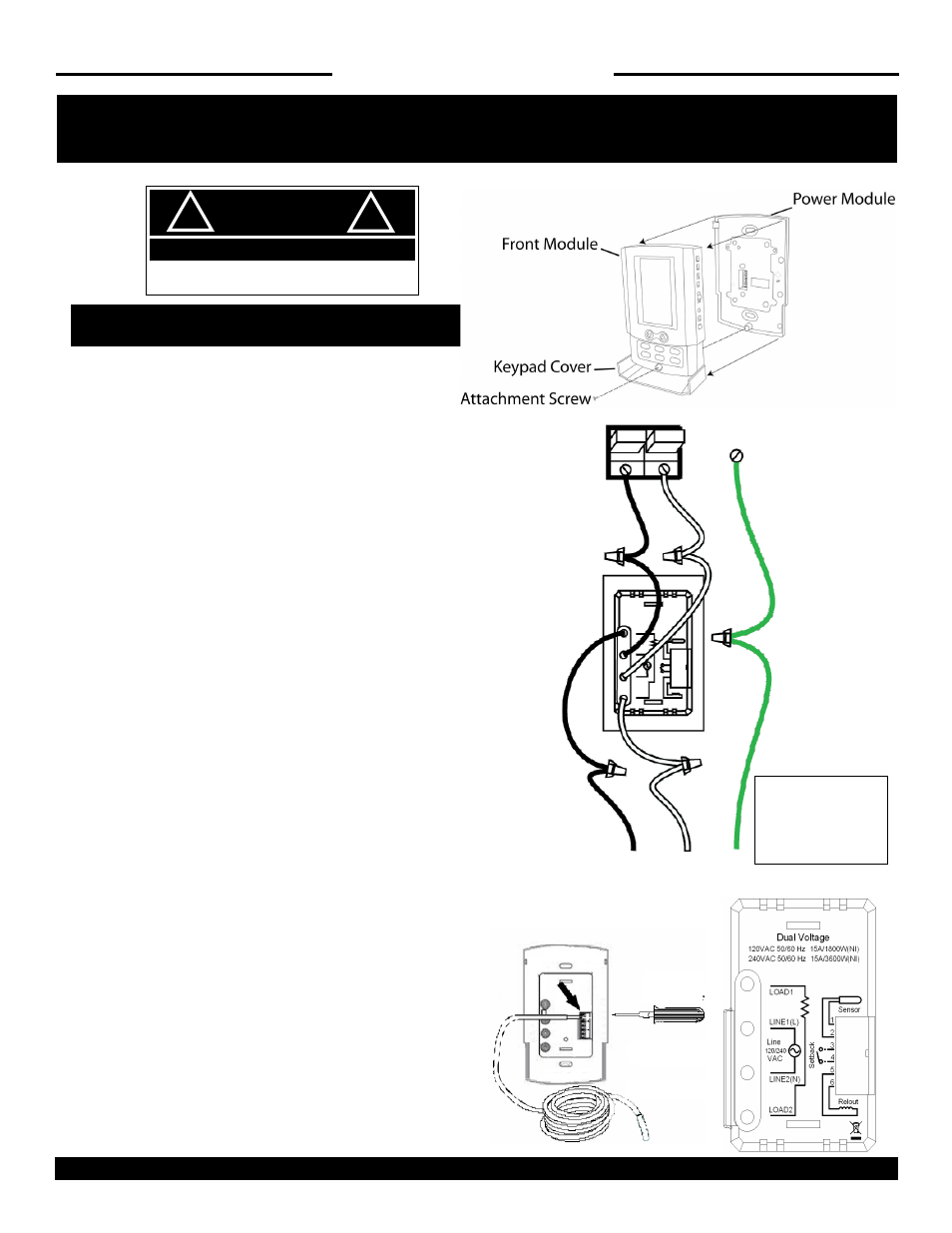
WIRING INSTRUCTIONS
1: Open keypad and loosen the screw on the bottom of the
front module. Pull gently from the bottom of thermostat
and lift to separate front module from power module.
2: Determine which pair of wires are coming from the
Breaker (supply wires) and which are going to the heater
(load wires).
3: Pull supply wires from wall box and for 120 VAC attach
black wire in box coming from the Circuit Breaker to Line1
(L) and white wire to Line2 (N). Secure with wire nuts.
For 240 VAC connect either supply wire to Line1 (L) then
connect other supply wire to Line2 (N) of the thermostat.
Secure with wire nuts.
4: Next take the black load wire from heater and attach it
to Load1 on thermostat. Then take the other load wire
coming from heater and attach it to Load2. Secure with
wire nuts.
5: Tie the braided ground wire from heater to ground wire
from the panel.
Floor Sensor Installation
6: Using a small flat head screwdriver loosen the
connection screws on the green terminal board on the
back of the power module. Insert both wires of the floor
sensor to the connector 1 and 2 and tighten screws.
7: Secure the power module onto the wall box with screws
and replace the front module securing with the screw.
SAVE THESE INSTRUCTIONS
INSTALLATION CON’T
DANGER
!
!
ELECTRIC SHOCK OR FIRE HAZARD
READ ALL WIRE SIZING, VOLTAGE REQUIREMENTS AND
SAFETY DATA TO AVOID PROPERTY DAMAGE AND
KING ELECTRIC MFG CO · 9131 10TH AVENUE SOUTH · SEATTLE, WA 98108 · PH:206 762 0400 · FAX: 206 763 7738 · www.king-electric.com
Line1 (L)
Black
Line2
(N)
White
Load1
Black
Load2
White
Ground
Wire
Small
Screwdriver
Floor Sensor
Note: 240V DP cir-
cuit breaker shown.
120V requires SP
circuit breaker