Sensor and alarm relay connections general, Temperature sensors – King Electric GPT 3 User Manual
Page 12
Page 12 of 21
wire size of 10 AWG with, minimum, 300 volt insulation rated for at least 75ºC.
Figure 2 shows a pictorial wiring diagram of the heater and supply voltage connections. Use
appropriately rated wire nuts or bomb splices for all heater and supply connections. Connect the
equipment safety ground and heater shield ground to the lug provided for this purpose.
Sensor and Alarm Relay Connections
General
The two temperature sensors are connected to the terminal block in the low voltage
compartment along with the connections to the reverse acting isolated SPDT alarm relay. Use
#18 AWG copper wire with insulation rated for 300 volt service for all Class 2 connections
unless otherwise noted. Using jacketed extension wiring, although convenient, is not necessary.
Using metallic conduit for extension wires is recommended. Never route Class 2 circuits in
the conduit used for supply and heater voltage circuits.
Temperature Sensors
Two identical temperature sensors are supplied with the GPT–3. Each is supplied with
20' (6m) of extension wire. For distances of up to 500' (152m), use #18 AWG copper wire and
#12AWG for up to 2,000' (610m). Temperature sensor connections are non-polar.
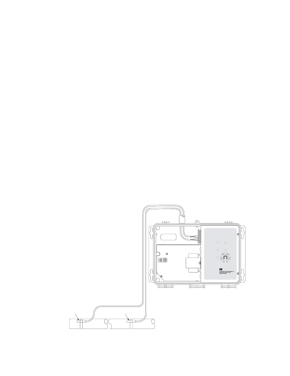
Systems using self-limiting heaters require two temperature sensors. Figure 3 shows
GPT
®
–3
TRACON
®
GFEP
FAULT
SUPPLY
HEATER
GFEP
RESET
TEST
HEATER
FAULT
Temperature
20
15
68
59
25
77
10
5
50
41
°C
°F
We Manage Heat
®
http://www.networketi.com
e-mail: [email protected]
®
J1
Monitor Temperature Sensor
Control Temperature Sensor
Low Voltage
Compartment
Figure 3. Control and monitor sensor connections for self-limiting heaters