King Electric Model KFUH User Manual
Page 2
2
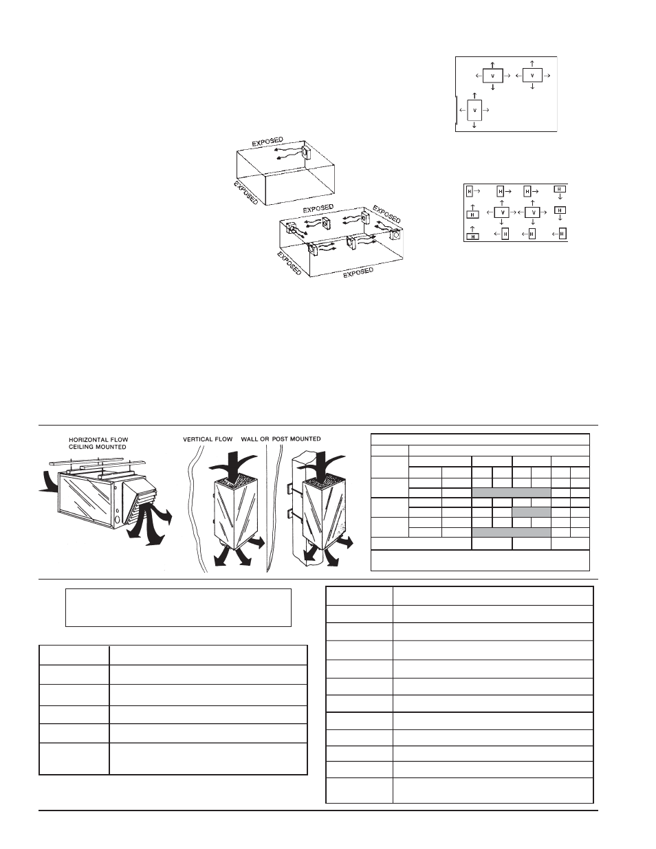
Mounting
KFUH heaters can be mounted vertically or
horizontally as shown. 3/8" weldnuts are weld-
ed into brackets and will accept 3/8 threaded
rod. A minimum of 6 inches clearance to
vertical and horizontal surfaces and 6 feet
minimum above floor are required. Louvers
can be adjusted for desired airflow.
Application Tips
First, calculate the heating loads in the con-
ventional way using the N.E.M.A. handbook or
ASHRAE guide. Next, determine quantity and
size of heaters to be used. In instances where
large groups of people are normally settled
in the same location, use a large number of
smaller kW unit heaters. (Example: people on
a production line or skilled machine opera-
tions.) By utilizing heaters in this manner one
can best distribute uniform heat, prevent hot
drafts, reduce potential noise levels and bal-
ance the electrical operating demand.
When considering warehouse areas or
storage rooms (where heat distribution and
constant temperatures are less important) use
fewer heaters of higher capacity.
To maintain uniform heat and reduce strati-
fied air it is recommended that the total CFM
of the units turn the air over approximately 3
times per hour.
Horizontal Mount
Smaller rooms can be heated by one unit
heater. Where two walls are exposed heaters
should be mounted as shown.
In larger rooms, units should be located so
their air streams wipe exposed walls without
blowing at them. Units should be located so
that the air stream of one supports that of
another thus setting up a circulatory air move-
ment. (Distance between units to be approxi-
mately 1½ times published air throw).
Units should not be mounted horizontally in
areas having ceiling heights in excess of 10
to 12 feet.
Vertical Mount
Units should be mounted vertically where
they may otherwise interfere with assorted
material, handling equipment and in high bay
areas. Heaters should be situated to provide
free air circulation. Size and selection of units
should be based on recommended mounting
height.
Unit heaters are frequently used to combat
cold air inrush when loading dock doors are
opened. For such applications, one or more
units should be arranged to blow warm air
vertically in front of opening.
Dual Mounting
Where square footage is large and comfort
essential, both horizontal and vertical installa-
tions may best serve your requirements.
Mounting Limitations
KFUH unit heaters should not be used in
potentially explosive atmospheres. The finish
is not intended for direct salt spray exposure
in marine applications or the highly corrosive
atmospheres of swimming pools, chemical
storage bins, etc. Please refer to the factory
for explosion proof or marine application
heater information.
Do not install unit heaters above recom-
mended maximum mounting height. Obstruc-
tions must not block unit heater air inlet or
discharge. To prevent possible injury heaters
must be mounted at least 6 feet above the floor
to prevent accidental contact with the heating
element or fan blade.
Adustable
Louvers
6" Minimum
Clearance
The following accessories and/or options
may have been ordered with your unit.
Add Suffi x
Description
-T
-2TS
-SF
-BR
1-Pole thermostat - factory installed
2-Stage thermostat - factory installed
Summer fan switch - factory installed
Blower relay for remote fan only operation
-2S1
-2S3
-DS40
-DS60
-DS80
-DS100
-ND
2-Stage control, 1-Phase models
2-Stage control, 3-Phase models
40 Amp 3-Pole non-fused disconnect switch
60 Amp 3-Pole non-fused disconnect switch
80 Amp 3-Pole non-fused disconnect switch
100 Amp 3-Pole non-fused disconnect switch
No diffuser - 1" duct collar provided on discharge
side for connection to 14" x 14" duct
2007 KFUH.indd : 3/08
Model
Description
KFUH-90D
KFUH-RD
KFUH-90RD
KFUH-PTBL
90 Degree Elbow w/ adjustable louver diffuser
Radial Diffuser
90 Degree Elbow w/ radial diffuser
Kit includes casters and mounting bracket to
create a Portable KFUH (no power cord)
1E30-910
24V Wall Thermostat, range 50°- 90°
Ceilings under 12 feet
Ceilings over 12 feet
AIR DELIVERY CHART @ .2 static
MOTOR SPEED
Motor HP
Motor Load
Low
Med
High
Voltage
Amps
CFM
FPM
CFM
FPM
FPM
CFM
1/5
230
380/460
3.4
1.7
775 570 860 630 1000 735
1/3
1/2
230
380/460
3.2
1.7
1100 810 1250 920 1540 1130
230
380/460
3.8
1.9
1250 920 1540 1130 1750 1285
Wire Color
Red
Blue
Black
Air Volume = Cubic Feet per Minute (CFM)
Air Velocity = Feet per Minute (FPM)
1000 735
1100 810
1540 1130
1750 1285