Installation instructions, Whfc - heater wiring diagram, Options – King Electric Model WHFC User Manual
Page 2: Features, Save these instructions
INSTALLATION INSTRUCTIONS
SAVE THESE INSTRUCTIONS
KING ELECTRICAL MFG. COMPANY • 9131 10th Ave So. • Seattle, WA 98108 • Ph: 206.762.0400 • Fax: 206.763.7738 • www.king-electric.com
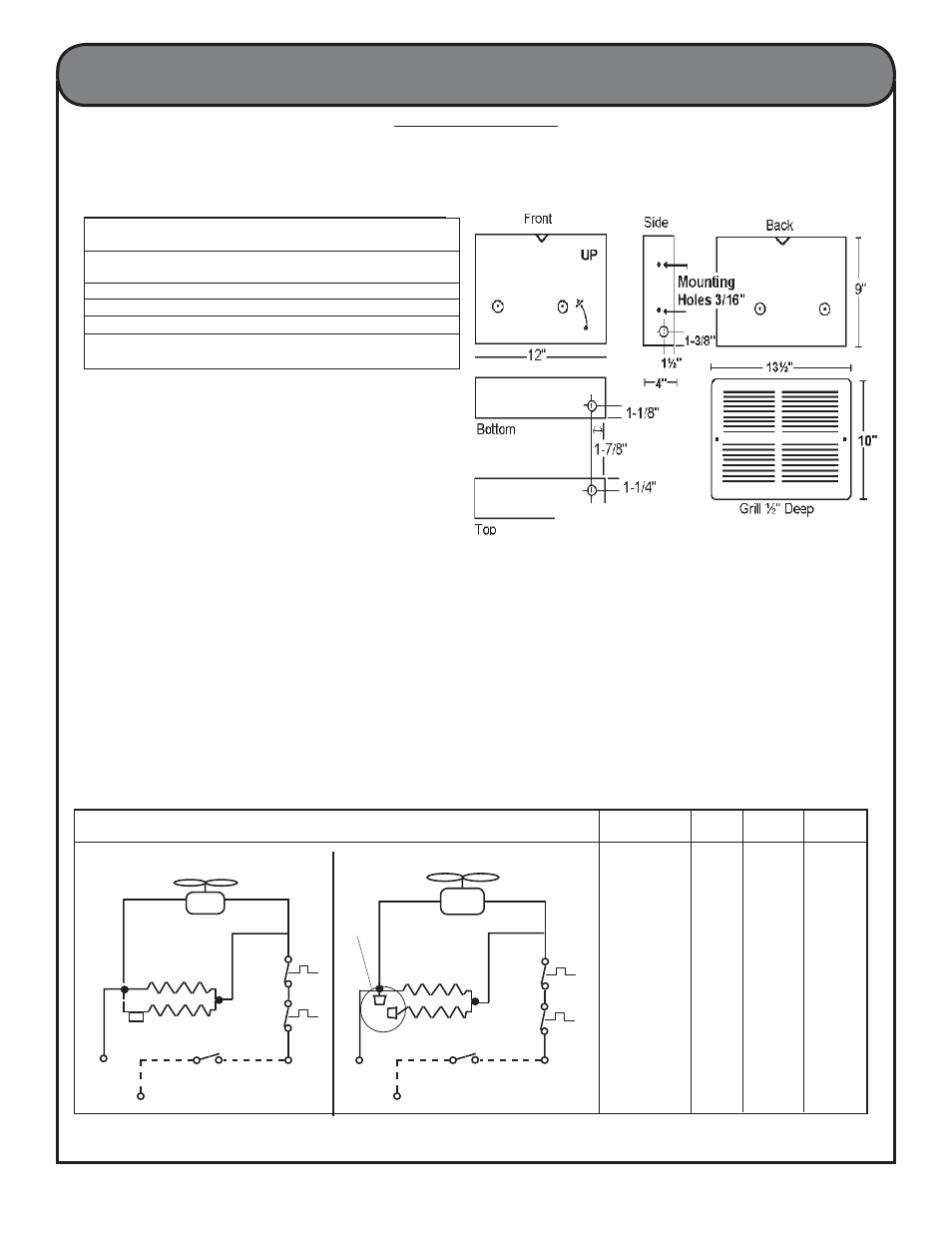
WHFC1210 120 1000 500
WHFC1212 120 1200 600
WHFC1215 120 1500 750
WHFC2410 240 1000 500
WHFC2415 240 1500 750
WHFC - HEATER WIRING DIAGRAM
MODEL
VOLTS
2-Element 1-Element
Wattage Wattage
OPTIONS
• A special powder-coated can may be purchased
for surface installation, model number WHSC-C.
FEATURES
• 500 to 1500 Watts (1706 - 5120 BTU)
• 120 - 208 - 240 voltages available
• 95 CFM tangential (squirrel cage) blower
• Large 75 cubic inch wiring compartment for easy
installation
• 20 gauge grill in white powder-coat fi nish
• Grill has large intake and outlet openings
• 20 gauge mounting wall can
• Elements are nickel chrome alloy coiled wire
wrapped around a mica insulator
• Motor is vibration isolated by a shock absorbing
rubber end cap
• Unique motor cooling system extends motor life
• Listed under UL2021 - standard for electric air
heating
MODEL VOLTAGE WATTAGE BTUH WT
WHFC2410
240
1000 or 500
3413 or 1706 8
208
750 or 375
2650 or 1280
WHFC2415
240
1500 or 750
5120 or 2650 8
208
1125 or 562
3840 or 1920
WHFC1210
120
1000 or 500
3413 or 1706 8
WHFC1212
120
1200 or 600
4095 or 2047 8
WHFC1215
120
1500 or 750
5120 or 2650 8
OPTIONAL
WHSC-C
Surface Mount Can
2
2007 WHFC.indd : 6/07
Install Heater NO LESS
than 16" From Vertical Walls
E1
E1
Single Element Factory Wiring
Two Element - Factory Wiring
ELEMENT
ELEMENT
TAG
LIMIT
LIMIT
LIMIT
LIMIT
FAN
E2
Capped
Ends
L 1
L 1
THERMOSTAT
(OPTIONAL)
L 2 POWER SUPPLY
L 2
THERMOSTAT
(OPTIONAL)
L 2 POWER SUPPLY
L 2
E2
FAN