Installation instructions, Lpw2445t, Save these instructions – King Electric Model LPWC User Manual
Page 2: Pic-a-watt, Field wattage selection
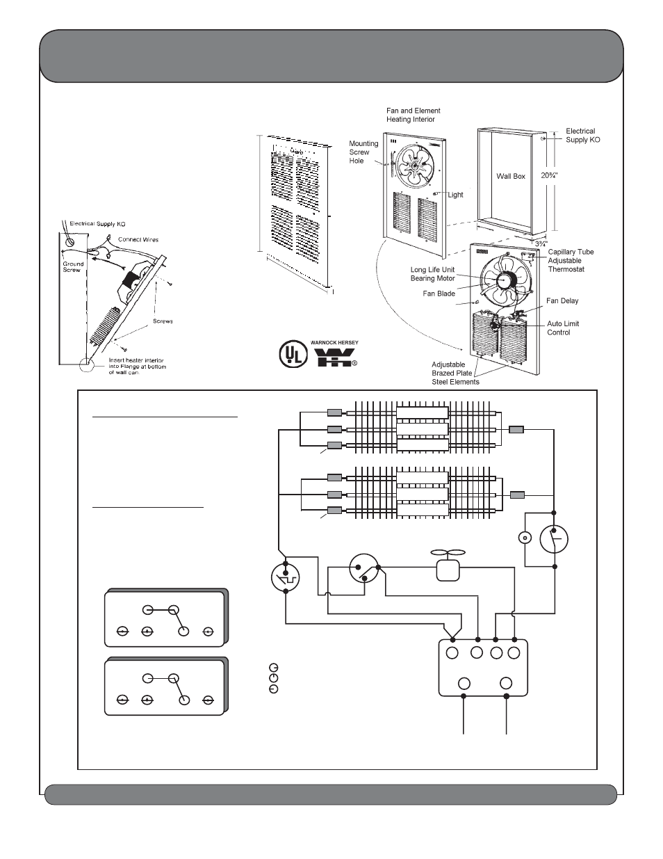
INSTALLATION INSTRUCTIONS
SAVE THESE INSTRUCTIONS
OWNERS GUIDE & INSTALLATION INSTRUCTIONS SHOULD BE LEFT WITH HEATER FOR HOME OWNER
KING ELECTRICAL MFG. COMPANY • 9131 10th Ave So. • Seattle, WA 98108 • Ph: 206.762.0400 • Fax: 206.763.7738 • www.king-electric.com
21¾"
13"
½"
This heater includes a visual alarm to
warn that parts of the heater are getting
excessively hot. If the alarm flashes
immediately turn the heater off and
inspect for any objects on or adjacent
to the heater that may cause high
temperatures. Do not operate the heater
with the alarm flashing.
Safety Light
LPW2445T.indd : 12/08
2250 • 2750 • 3000 • 3250 • 3750 • 4000 • 4500
WATTAGES AVAILABLE IN ONE UNIT
INSTALLATION INSTRUCTIONS
This heater is shipped from the factory
wired for maximum wattage of 4500
Watts at 240 Volts. To reduce the watt-
age unplug (disconnect) an insulated
push on terminal and wrap with electri-
cal tape to prevent the possibility of
electrical contact with other parts.
Field Wattage Selection
A - ORANGE Disconnects 1000 Watts
B - BLUE Disconnects 750 Watts
C - YELLOW Disconnects 500 Watts
D - BLACK Do Not Disconnect (Common)
E - RED Do Not Disconnect
END VIEW OF ELEMENT
SHOWING QUICK CONNECT TERMINALS
A
E
D Common
1000
E
E
C
D Common
1000
B
750
500
500
750
LPW2445T
11½"
Insulated Push on
Terminal
A
BLUE
FAN
DELAY
BLACK
1000 WATT
500 WATT
RED
YELLOW
C
B
E
ORANGE
RED
RED
E
E
BLACK #14
750 WATT
500 WATT
750 WATT
LIMIT
RED #14
BLACK #14
BLACK #16
BLACK#16
1
2
3
4
L2
BLACK
ORANGE #14
RED #14
GRAY #16
PURPLE #16
FAN
Insulated Push on
Terminal
knob position OFF.......L1-0, L2-0
knob position FAN.......L1-2, L2-4
knob position HEAT......L1-1, L2-4, L2-3
Thermostat
1000 WATT
Rotary Switch
L1
L1
L2
SAFETY
LIGHT
D
D
Pic-A-Watt
®
Metal Sheath Element
CONNECTIONS
2
3
1
FAN DELAY
1-3 N.C., 1-2 N.C.
1-2 Closes on Temp Rise