KB Electronics KBWT-210 User Manual
Page 4
KBWT Series Installation and Operation Instructions
(A40130) – Rev. B00 – 5/29/2013
Page 4 of 7
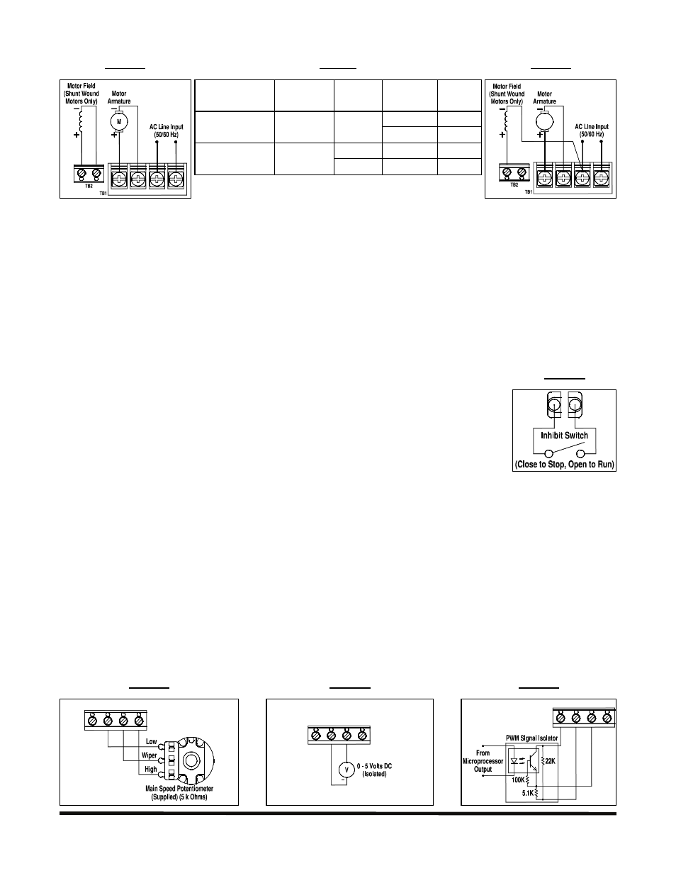
3.5 Motor Field (Shunt Wound Motors Only): Connect the motor field as described in Sections 3.5.1 and 3.5.2.
FIGURE 3
FULL VOLTAGE FIELD
TABLE
3
FIELD CONNECTION (SHUNT WOUND MOTORS ONLY)
FIGURE
4
HALF VOLTAGE FIELD
Model
AC Line
Input Voltage
(Volts AC)
Armature
Voltage
(Volts DC)
Field Voltage
(Volts DC) Terminals
100
F+ and F-
KBWT-16, 110, 112
115
0 – 90
50
F+ and L1
0 – 180
200
F+ and F-
KBWT-26, 210
208/230
0 – 90*
100
F+ and L1
F+ F−
A+
A−
L1
L2
*Step-down operation.
F+ F−
A+
A−
L1
L2
M
Notes: 1. Do not use field terminals for any purpose other than to power the field of a shunt wound motor. 2. Do
not connect motor armature to the field terminals. 3. Shunt wound motors may be damaged if the field remains
energized without armature rotation for an extended period of time.
3.5.1 Full Voltage Field: For 90 Volt DC motors with 100 Volt DC field and 180 Volt DC motors with 200 Volt DC
field. Connect the field positive (+) lead to TB2 Terminal F+ and the field negative lead (-) to TB2 Terminal F-, as
shown in Figure 3 and Table 3, above.
3.5.2 Half Voltage Field: For 90 Volt DC motors with 50 Volt DC field and 180 Volt DC motors with 100 Volt DC
field. Connect the field positive lead (+) to TB2 Terminal F+ and the field negative lead (-) to TB1 Terminal L1, as
shown in Figure 4 and Table 3, above.
3.6 Inhibit Switch or Contact: The drive can be electronically stopped and started with
an Inhibit switch or contact connected to TB3 Terminals I1 and I2. When the switch or
contact is closed, the drive motor will coast to stop. When the switch or contact is opened,
the motor will run at the Main Speed Potentiometer or signal input setting. See Figure 5.
3.7 Signal Input: The drive can be operated with a 5 kΩ Main Speed Potentiometer
(supplied), an isolated 0 – 5 Volt DC analog signal, or an isolated Pulse Width Modulated
(PWM) signal from a microprocessor.
Note: If an isolated signal is not available, an optional signal isolator must be installed (KBSI-240D
(Part No. 9431) or equivalent).
3.7.1 Main Speed Potentiometer:
Connect the potentiometer low side
to Terminal P1, the wiper to
Terminal P2, and the high side to
Terminal P3. See Figure 6.
3.7.2 Voltage Following Signal:
An isolated 0 – 5 Volt DC analog
voltage signal can be used to
control motor speed. Connect the
isolated voltage signal positive (+)
lead to Terminal P2 and the
negative (-) to Terminal P1. See
Figure 7.
3.7.3 Microprocessor Signal:
An isolated PWM signal from a
microprocessor can be used to
control motor speed. The
output frequency should be 200
Hz or higher and should be
derived from an optocoupler
with a transistor or operational
amplifier signal output. See
Figure 8.
FIGURE 6
MAIN SPEED POTENTIOMETER
FIGURE 7
VOLTAGE FOLLOWING SIGNAL INPUT
FIGURE 8
MICROPROCESSOR SIGNAL INPUT
V+ P1 P2 P3
TB3
+
V+ P1 P2 P3
TB3
V+ P1 P2 P3
TB3
FIGURE 5
INHIBIT
I1
I2