IDEC MicroSmart AS-i User Manual
Page 43
6: AS-I
NTERFACE
O
PERANDS
6-12
M
ICRO
S
MART
AS-I
NTERFACE
M
ASTER
M
ODULE
U
SER
’
S
M
ANUAL
HW Series Digital I/O Data Allocation
Input data is sent from slaves to the AS-Interface master. Output data is sent from the AS-Interface master to slaves.
Notes:
1.
∗ The AS-Interface master uses bit DO3 for addressing A/B slaves.
2. In the above table, bits marked with X1, X2, and X3 are used for SwitchNet I/O data.
3. X1: When pushbutton is pressed, input data is 1 (on). When not pressed, input data is 0 (off). When output data is 1
(on), LED is on. When output data is 0 (off), LED is off.
4. X2: The input data from 2-position selector, key selector, and illuminated selector switches depend on the operator posi-
tion as shown below.
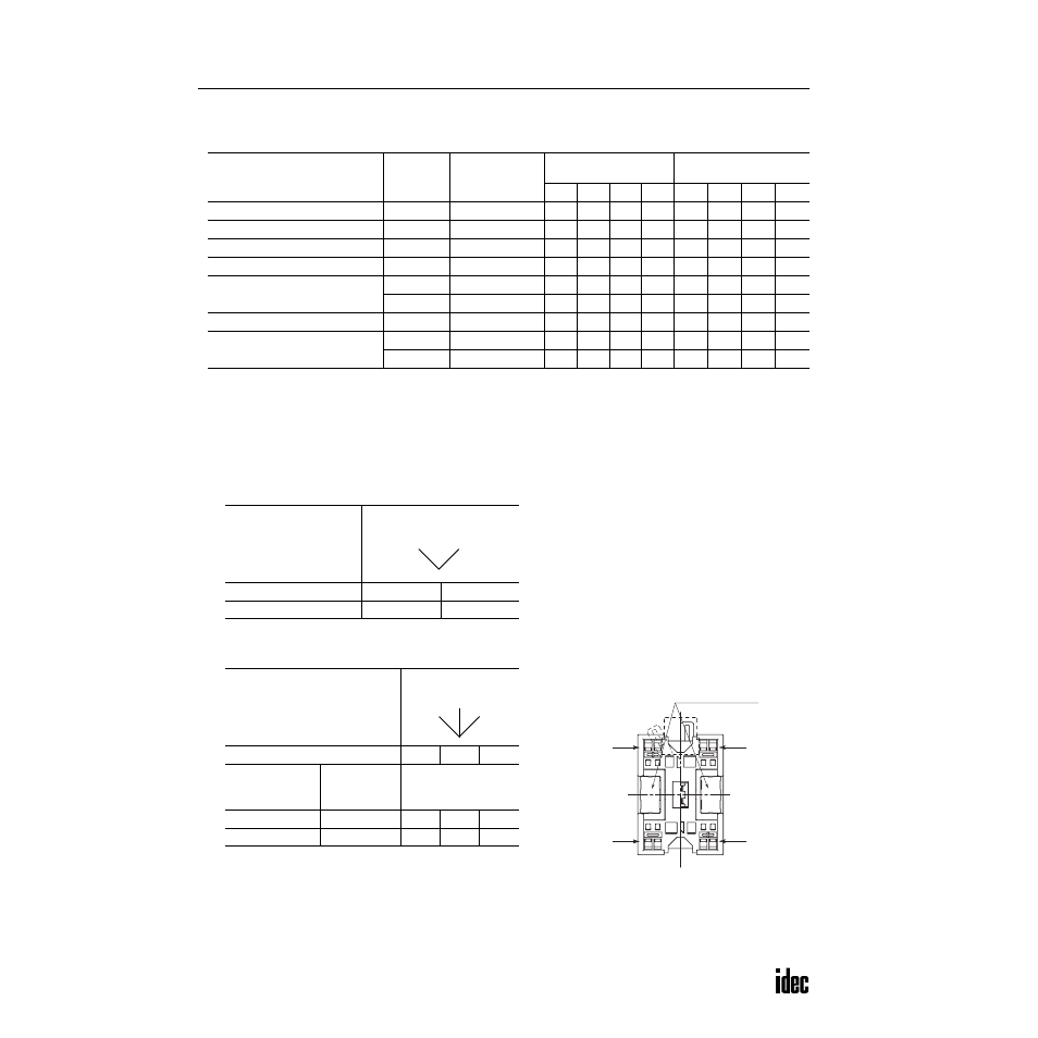
5. X3: The input data from 3-position selector, key selector, and illuminated selector switches depend on the operator posi-
tion as shown below.
As shown in the table and figure, 3-position selector, key
selector, and illuminated selector switches use two communi-
cation blocks. Each communication block must have a unique
address, therefore the 3-position selectors require 2 slave
addresses.
6. Unused input bits DI3 and DI2 are 0 (off), and unused input bits DI1 and DI0 are 1 (on). Slaves ignore unused output
data (—) sent from the master.
SwitchNet HW Series
Slave Unit
Used I/O
Communication
Block Mounting
Position
Input Data
(slave send data)
Output Data
(slave receive data)
DI3
DI2
DI1
DI0
DO3
DO2
DO1
DO0
Pushbutton
1 in
➁
0
X1
1
1
*
—
—
—
Pilot light
1 out
➁
0
0
1
1
*
—
—
X1
Illuminated pushbutton
1 in/1 out
➁
0
X1
1
1
*
—
—
X1
Selector, Key selector: 2-position
1 in
➁
0
X2
1
1
*
—
—
—
Selector, Key selector: 3-position
1 in
➀
0
X3
1
1
*
—
—
—
1 in
➁
0
X3
1
1
*
—
—
—
Illuminated selector: 2-position
1 in/1 out
➁
0
X2
1
1
*
—
—
X1
Illuminated selector: 3-position
1 in
➀
0
X3
1
1
*
—
—
—
1 in/1 out
➁
0
X3
1
1
*
—
—
X1
2-position Operator
Operator Position
1
2
DI2
0
1
3-position Operator
Operator Position
1
0
2
Communication
Block Mounting
Position
Input Data
Bit
➀
DI2
1
0
0
➁
DI2
0
0
1
1
2
Selector
Left
Right
Address Marking Area
Mounting
Position
➀
Mounting
Position
➁
AS-i (–)
AS-i (–)
AS-i (+)
AS-i (+)
Communication Block Mounting Position
(Rear View)
On 3-position selector, key selector, and illuminated
selector switches, communication blocks ➀ and ➁
are mounted in positions shown above.
1
2
0
Selector
Left
Right
Center