As-interface cable wiring, Power supply – IDEC MicroSmart AS-i User Manual
Page 19
3: I
NSTALLATION
AND
W
IRING
3-6
M
ICRO
S
MART
AS-I
NTERFACE
M
ASTER
M
ODULE
U
SER
’
S
M
ANUAL
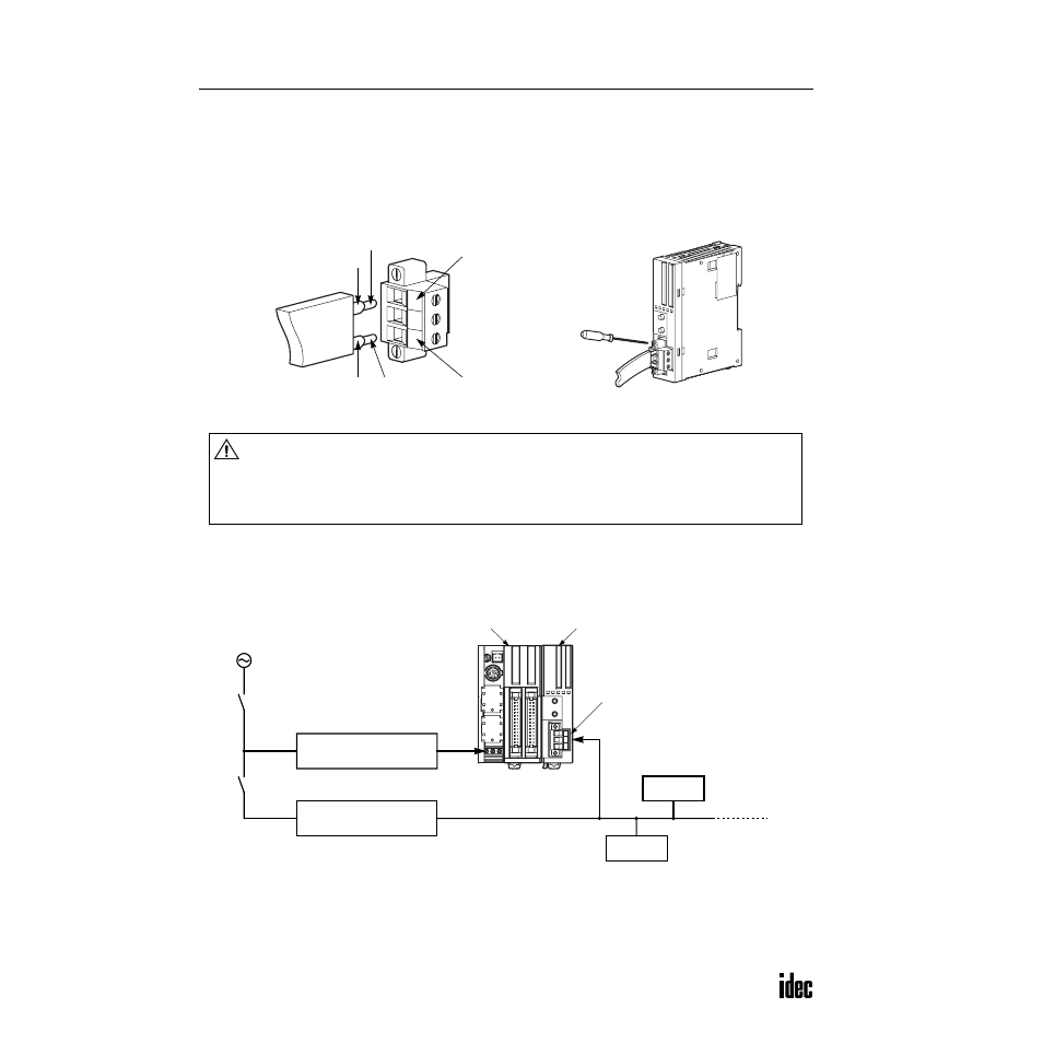
AS-Interface Cable Wiring
Before wiring the AS-Interface cable, remove the AS-Interface cable terminal block from the AS-Interface cable connector
on the AS-Interface master module.
AS-Interface specifies use of brown cables for the AS-Interface + line, and blue cables for the AS-Interface – line. Connect
the cables to match the color labels on the terminal block. Tighten the terminal screws to a torque of 0.5 to 0.6 N·m.
Insert the terminal block to the connector on the AS-Interface master module, and tighten the mounting screws to a torque
of 0.3 to 0.5 N·m.
Power Supply
Power Supply Wiring Diagram
A recommended power supply wiring diagram is shown below. Use a common power switch for both the CPU module
power supply and AS-Interface power supply to make sure that both power supplies are turned on and off at the same time.
Note: A failed slave can be replaced with a new slave with address 0 without turning off the power to the CPU module and
the AS-Inter face line. But, if power has been turned off before replacing the slaves, install a new slave with address 0 and
take one of the following steps, because the AS-Inter face master module has to be initialized to enable communication.
•
Disconnect the AS-Inter face cable connector and turn on both power supplies. Five seconds later, connect the AS-Inter face
cable connector.
•
Turn on the CPU module power supply first. Five seconds later, turn on the AS-Inter face power supply.
Blue AS-Inter face –
Use a ferrule.
Brown AS-Inter face +
Use a ferrule.
Blue Label
Brown Label
Caution
• When turning off the power to the CPU module, also turn off the AS-Interface power supply. If
the CPU module is powered down and up while the AS-Interface power remains on, AS-Interface
communication may stop due to a configuration error, resulting in a communication error.
• Turn on the AS-Interface power supply no later than the CPU module power supply, except when
slave address 0 exists on the network. The two power supplies may be turned off in any order.
AS-Interface Power Supply
30V DC
Slim Type CPU Module
FC4A-D40K3
AS-Inter face Master Module
FC4A-AS62M
Slave 1
Slave 2
AC Power
CPU Module Power Supply
24V DC
Power Switch
AS-Inter face Power Switch (Note)
AS-Inter face Cable Connector
VLSV (ver y low safety voltage)