Parts description – IDEC MicroSmart AS-i User Manual
Page 11
2: M
ODULE
S
PECIFICATIONS
2-2
M
ICRO
S
MART
AS-I
NTERFACE
M
ASTER
M
ODULE
U
SER
’
S
M
ANUAL
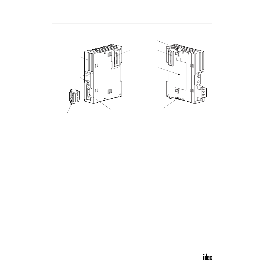
Parts Description
(1) LED Indicators
Status LEDs:
Indicate the AS-Interface bus status.
I/O LEDs:
Indicate the I/O status of the slave specified by the address LEDs.
Address LEDs:
Indicate slave addresses.
(2) Pushbuttons
Used to select slave addresses, change modes, and store configuration.
(3) AS-Interface Cable Terminal Block
Connects the AS-Interface cable.
One terminal block is supplied with the AS-Interface master module.
When ordering separately, specify Type No. FC4A-PMT3P and quantity
(package quantity: 2).
(4) AS-Interface Cable Connector
Installs the AS-Interface cable terminal block.
(5) Unlatch Button
Used to unlatch the AS-Interface master module from the CPU or I/O module.
(6) Expansion Connector
Connects to the CPU and other I/O modules.
(Applicable CPU modules are 20-I/O relay output and 40-I/O slim types.)
(7) Module Label
Indicates the AS-Interface master module Type No. and specifications.
(6) Expansion Connector
(7) Module Label
(1) LED Indicators
(4) AS-Inter face Cable Connector
(2) Pushbuttons
PB1
PB2
(5) Unlatch Button
(5) Unlatch Button
(3) AS-Inter face Cable Terminal Block
(supplied with the AS-Inter face master module)