C. locating the water heater – HTP EVC115 User Manual
Page 7
7
LP-379 REV. 3.25.14
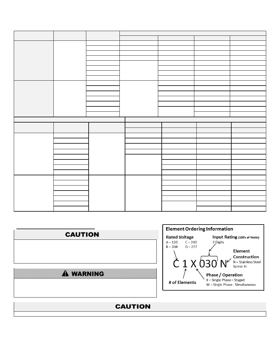
GALLONS
# ELEMENTS
AVAILABLE
WATTAGE
VOLTAGE (ELEMENT KIT PART #)
120
208
240
277
10, 15, 20
1
1,500
A1X015N
B1X015N
C1X015N
D1X015N
2,000
A1X020N
B1X020N
C1X020N
D1X020N
2,500
A1X025N
B1X025N
C1X025N
D1X025N
3,000
A1X030N
B1X030N
C1X030N
D1X030N
3,500
-
B1X035N
C1X035N
D1X035N
4,000
B1X040N
C1X040N
D1X040N
4,500
B1X045N
C1X045N
D1X045N
5,000
B1X050N
C1X050N
D1X050N
30, 40, 50,
80, 115
2
6,000
-
B2W060N
C2W060N
D2W060N
7,000
B2W070N
C2W070N
D2W070N
8,000
B2W080N
C2W080N
D2W080N
9,000
B2W090N
C2W090N
D2W090N
10,000
B2W100N
C2W100N
D2W100N
11,000
-
C2W110N
D2W110N
12,000
C2W120N
D2W120N
FULL LOAD CURRENT IN AMPS
GALLONS
INPUT
WATTAGE
# OF
THERMOSTATS
120 volts
208 volts
240 volts
277 volts
Single Phase
Single Phase
Single Phase
Single Phase
10, 15, 20
1,500
1
13
8
7
6
2,000
17
10
9
8
2,500
21
13
11
10
3,000
25
15
13
11
3,500
-
17
15
13
4,000
20
17
15
4,500
22
19
17
5,000
25
21
19
30, 40, 50,
80, 115
6,000
2
-
30
26
22
7,000
34
30
26
8,000
40
34
30
9,000
44
38
34
10,000
50
42
38
11,000
-
46
40
12,000
50
44
Table 2
– Listing of Elements and Corresponding Voltages / Wattages / Amperages
C. LOCATING THE WATER HEATER
Locate the water heater where any leakage from the relief valve, related
piping, tank, or connections will not result in damage to surrounding areas
or lower floors of the building. The water heater should be located near a
floor drain, or installed in a drain pan. HTP WILL NOT be held liable for
leakage damages.
Incorrect ambient conditions can lead to damage to the heating system and
put safe operation at risk. Ensure that the installation location adheres to
the information included in this manual. Failure to do so could result in
property damage, serious personal injury, or death.
Failure of water heater or components due to incorrect operating conditions IS NOT covered by product warranty.
1. Installation Area (Mechanical Room) Operating Conditions
Ensure ambient temperatures are higher than 32
o
F/0
o
C and lower than 104
o
F/40
o
C.
Avoid continuously high levels of humidity