Notice – Harrington Hoists and Cranes SHB Trolley User Manual
Page 11
11
3.0 Preoperational Procedures
3.1 Trolley
Adjustment
3.1.1
NOTICE
Before use, the trolley can be adjusted in increments of 1/8” by simply inserting or
removing adjusting spacers to fit a variety of beam flanges. Adjustments must be made to the Upper
Suspension Shaft and to the Lower Suspension Shaft.
3.1.2
To adjust the Upper Suspension Shaft reference
Figure 3-1
and
Table 3-2
. Proceed with the following
instructions:
1. Remove all of the suspension shaft bolts.
2. Shift both the handwheel (Side Plate G) and manual chain hoist (Side Plate S) collars to the
appropriate hole positions according to the selected beam width. Reinsert the appropriate number
of inner spacers for the desired flange width as indicated in
Table 3-2
.
3. “Inner” means between the side plates and “outer” means outside of the side plates.
4. For designations such as “X + Y”, “X” is on the trolley hand wheel side and “Y” is on the hoist side.
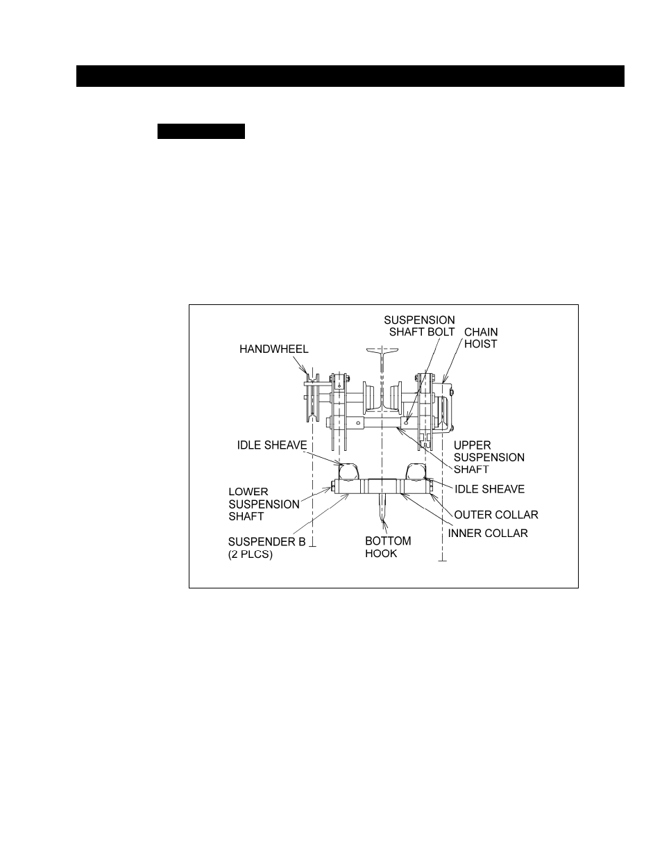
Figure 3-1
Trolley Side Plate Assembly
3.1.3
To adjust the Lower Suspension Shaft reference
Figure 3-1
and
Table 3-3
. Proceed with the following
instructions:
1. Remove all of the lower suspension shaft pins.
2. To make the adjustment, replace the inner and outer collars as shown in
Figure 3-1
.
3.
Table 3-3
provides the spacer arrangement information. Take note of the number of spacers
on the “inner” side.
4. “Inner” means between the suspender “B’s”, and “outer” means outside of the suspender “B’s”.
5. For designations such as “X + Y”, “X” is on the trolley hand wheel side and “Y” is on the hoist
(CB) side.