Harrington Hoists and Cranes MR Trolley - (MR2) User Manual
Page 18
Note: Inner Spacer rows on Table 3-2 list two numbers. First number is the quantity of spacers located on the
left side of the Suspender or Suspension Plates, second number is the quantity on the right side.
Example: 1 + 2
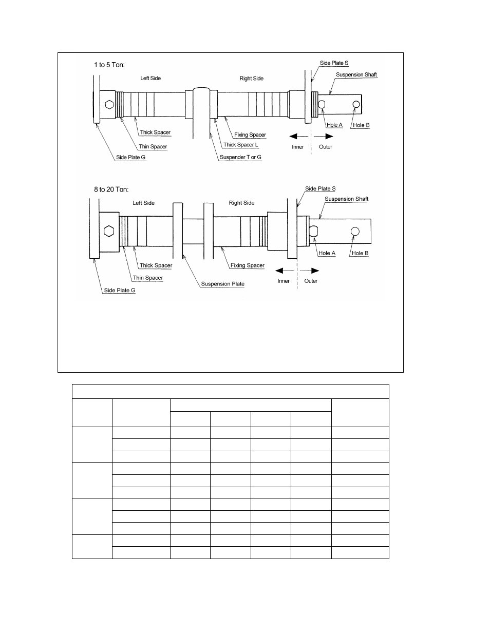
Adjusting Spacers on the right side (Side Plate S side)
Adjusting Spacers on the left side (Side Plate G side)
Figure 3-10 Spacers Arrangement
Table 3-1 Suspension Shaft Adjusting Spacers, and Suspension Shaft Bolt
Capacity
(Tons)
Flange Range
(in)
Total Number of Spacers Supplied
Suspension
Shaft Bolt
Location
Thin
Thick
Fixing
Thick L
1
2.28 to 5.00
8
3
2
Hole 2
5.01 to 6.02
8
5
2
Hole 1
6.03 to 12.00
8
9
2
2
Hole 1
2 & 3
3.23 to 6.02
8
3
2
Hole 2
6.03 to 7.02
8
5
2
Hole 1
7.03 to 12.00
8
9
2
2
Hole 1
5
3.94 to 7.01
8
3
2
Hole 2
7.02 to 7.60
8
4
2
Hole 1
7.61 to 12.00
8
13
2
Hole 1
8 and up
5.91 to 8.66
8
6
Hole 1
8.67 to 12.00
8
7
2
Hole 1
18