Gillette Generators SPP-180 User Manual
Page 13
PAGE 13
EXAMPLE 2: A model SPP-180, 16 KW generator is to
be installed 50 feet from gas meter. In reading the
charts, Fig. 1 shows this model to require 280 cubic
feet/hour (or 280,000 BTU/hr) gas volume to be
delivered to generator. Figure 2 chart show this
required 280 cu.ft. can not be delivered with a ¾” or
1” pipe. Only a 1¼” diameter pipe can safely deliver
the 280 cu.ft. gas requirement, over a 50 foot
distance.
INSTALLER’S RESPONSIBILITY: Use Figure 1
chart to learn cubic feet/hour value of generator to
be installed. Use Figure 2 chart to learn minimum
pipe size diameter and maximum distance from
gas meter, to insure sufficient fuel volume from
natural gas meter to generator set.
CRITICAL POINTS FOR A PROPER
NATURAL GAS INSTALLATION
Before natural gas fuel line plans are made, call
your natural gas supplier, give information on the
amount of cubic feet/hour and the BTU’s/hour that
generator will use, and ask if natural gas meter and
primary regulator, is adequate for your natural gas
generator. Natural gas companies have different
meters for increasing BTU gas demands.
Check the natural gas primary regulator,
connected at natural gas meter output. The correct
primary regulator is set at 6 to 8 inches water column
(4 to 4½ ounces pressure or 0.19 to 0.26 PSI). The
existing primary regulator (for other gas appliances)
may be too small to run your gas driven generator.
A dedicated natural gas fuel line and primary
gas regulator (if required) is mandatory for proper
operation.
A flexible natural gas fuel line is furnished for
installation between utility gas line and generator for
input.
CAUTION: Make sure this flexible fuel line is
installed in horizontal position without bends. A
bend of any kind in this flexible line could lead to
an eventual crack in the bend, causing a possible
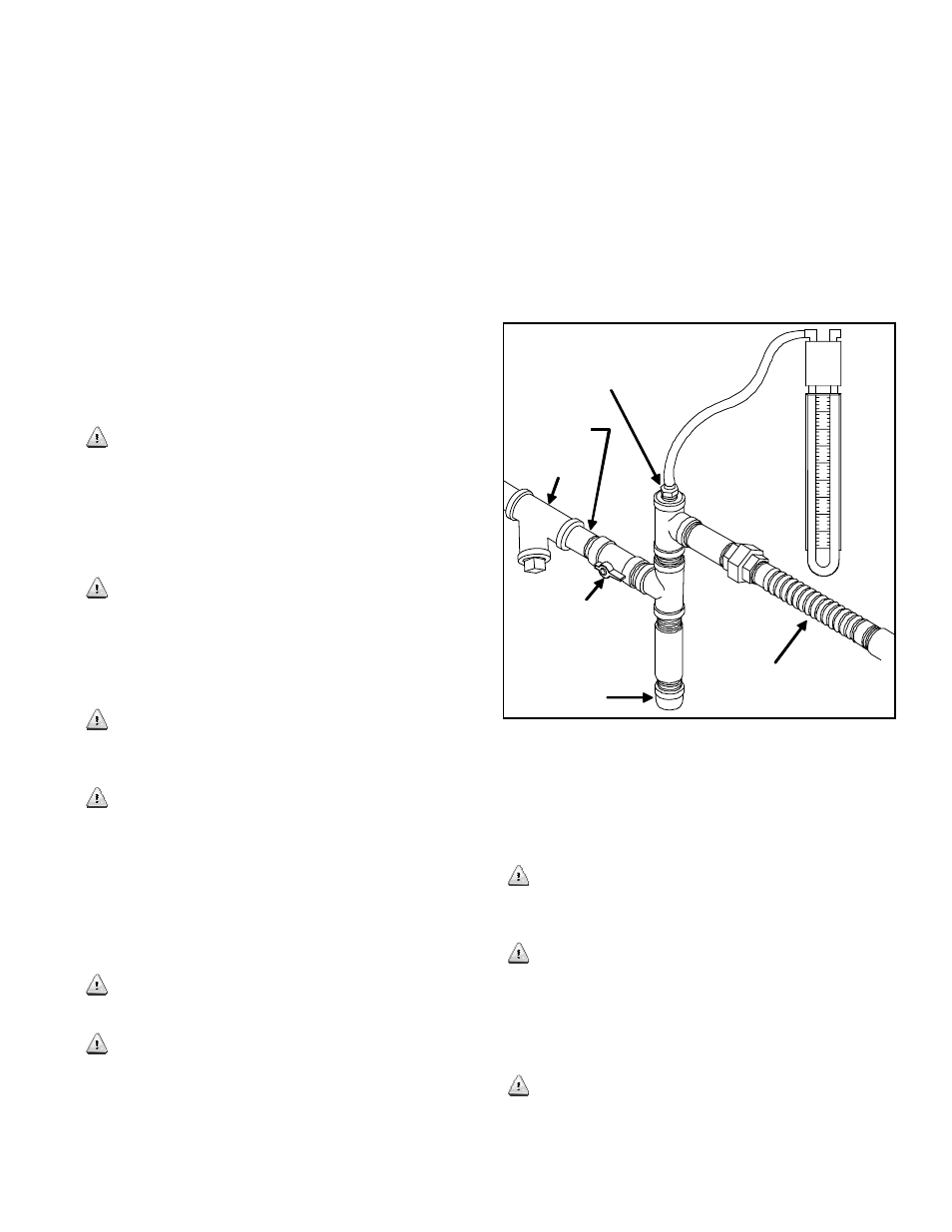
leak. See Figure 3 for a recommended installation.
Make sure fuel pipe installation and connection at
generator includes an on/off manual gas valve.
All new installations, plus any future repair or
troubleshooting procedures must include a natural
gas manometer test. This test should be conducted
after all other natural gas appliances have been
turned on. After all appliances are running, start the
generator. If manometer stays within 6 to 7 inches
water column with full load applied to a proper
running generator, it’s a good installation. (See
Figure 3)
If manometer reading falls below 5 inches water
column while generator engine is cranking, or
running, it may indicate the gas meter or primary
regulator is too small, or the fuel pressure from gas
supplier is inadequate. Any of these three problems
will cause a fault in proper generator operation.
If manometer reading stays within the 6 to 7 inches
water column, but generator engine still will not start,
or it runs erratic, it may indicate insufficient fuel
volume due to long fuel line runs or fuel pipe
diameter is too small. Check calculations of chart in
Figure 1 & 2.
Figure 3
NOTE: After completion of all gas tests, remove
manometer and replace blank plug, using fresh pipe
sealant.
For additional precautions, a manual fuel shut-off
valve should also be installed inside the building, for
those locations with inside gas meters.
Climates that have snow and ice build-up, along
with sub-zero temperatures, should have gas fuel
piping protection against freezing. The generator
end of the hard piping installation should include a
sediment trap to drain any condensation, and a line
filter. (See Figure 3)
Best installations happen when electric utility
meter and gas meter are close together, as it results
in short runs for both electric wires and fuel lines.
When these two utilities are far apart, always choose
to locate gen-set close to the gas meter, as installation
Sediment Trap
Dedicated
Natural Gas
Fuel Line
Manometer
Reading
Must Be 6”
to 7” Water
Column
Gas Fuel To
Generator
On/Off Valve
Furnished
Flexible
Gas Pipe
(without
bends or
angles)
Manometer Port: Remove
Blank Plug And Insert
Manometer Plug
Line Filter