Gilderfluke&Co Back to the Future User Manual
Page 3
Japan dashboards. These are organized to retain compatibility with the California dashboards.
A Real Time Clock chip which has been laser trimmed for an accuracy of +/-10 PPM pro-
vides the clock data for the display. A battery retains RTC data when the car is powered
down. The firmware we have written will automatically adjust the clock to daylight savings time
if desired and the turn of the millennium after 1999. In the last three years, the California in-
stallation has only rarely needed to adjust the clocks in their retrofitted attraction.
The two eight position RJ-45 connectors provide the digital outputs needed to run the
lights on the keypad (four digital outputs) and LEDs in the Flux Capacitor (three digital
outputs). The output capacity of these eight outputs is 150 ma continuous, 500 ma peak.
These outputs are powered by the fifteen VDC that runs the dashboard.
The two six position RJ-12 connectors provide the 0-10 volt analog outputs needed to run
the meters on the speedometer (one PWM backlighting brightness and two analog outputs)
and Roentgen Gauges (three analog outputs). Five analog outputs are needed in total. A 2.5
volt, thermally stable reference is generated in the LM336-2.5. This is buffered and sent
through the DAC. The outputs of the DAC is amplified to 0-10 volt levels and sampled (and
held) in the SMP-18. The final outputs is then buffered by the two LM324s before sending the
voltages out to the gauges.
Four eight bit channels of animation data (three seven segment displays and one bright-
ness command) are transmitted serially through the four position RJ-08 connector for use by
the E-Speedo display. This data is transmitted at 9600 baud using RS-422 signal levels.
A RS-232 port is provided for configuring the BttF2. Connection is via a standard DE-09
connector that extends from the bottom of the time display assembly.
The DMX-512 port is used to receive data from PC•MACs animation control systems for
programming the Back to the Future Japan CPU. It can also be used to receive animation
data from a Togglodyte test tool for field servicing the display and attached components.
Connection is via a standard miniature five position Mini-DIN connector that extends from the
bottom of the time display assembly.
Two optically isolated inputs are provided. A dipswitch can select between Japan and
California/Florida style starts. These inputs have resistors in series with them to be used with the
24 VDC inputs from the PLC.
Two optically isolated outputs are provided. These output animation data from the shows
that can be used as hearts or running status indicators. Currently, one is programmed to flash
at 2 Hz during the main show, and the other flashes at 2 Hz during the load/unload show.
The BttF2 design uses a 3 amp rated integrated switching regulator for powering both the
LED displays and the CPU printed circuit boards.
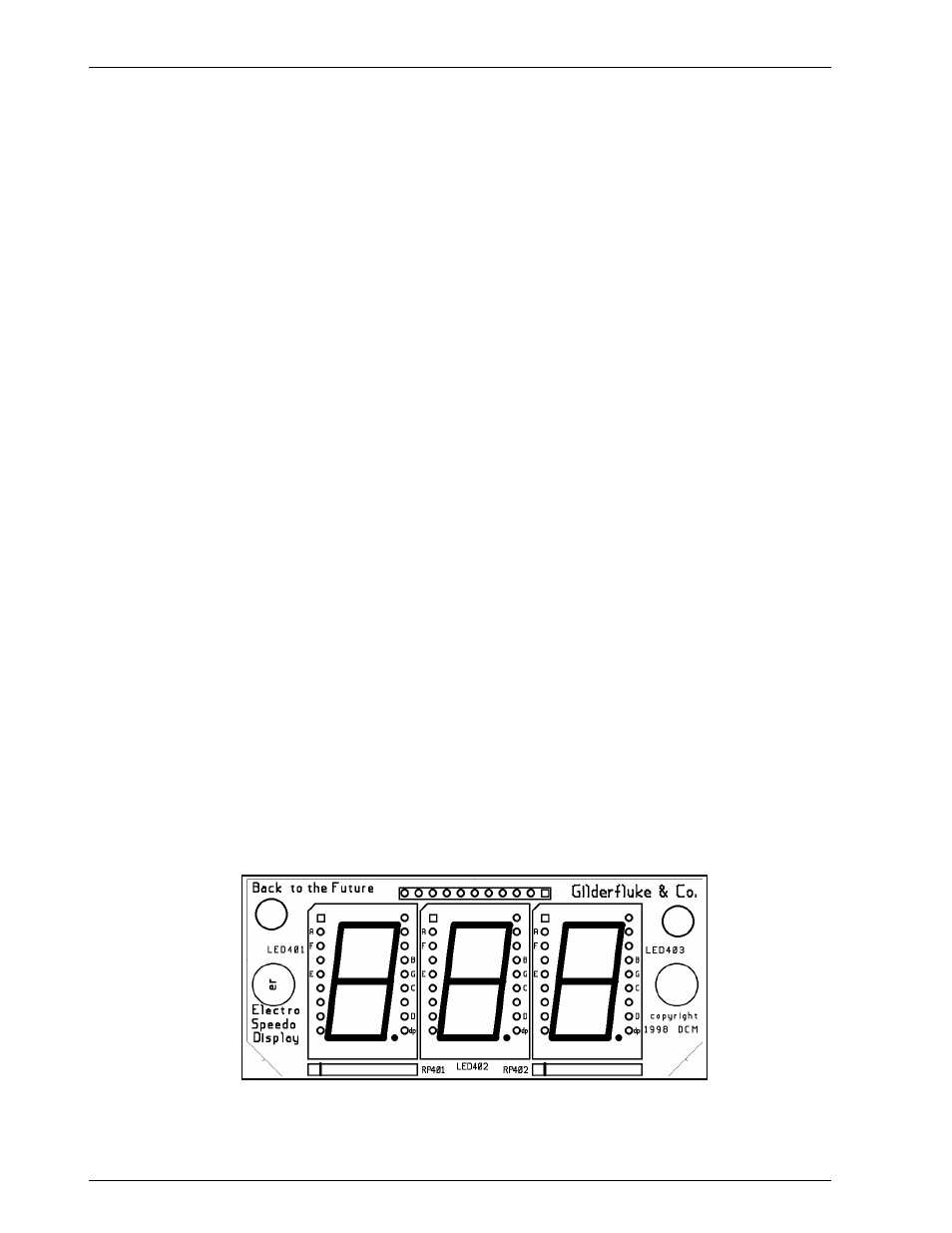
3) E-Speedo Display: This printed circuit board has three .8” tall yellow seven segment displays on
it. As with the time display printed circuit board, much higher quality displays are being used
for a potentially much brighter display than in either of the original attractions.
G
ILDERFLUKE
& C
O
. • 205 S
OUTH
F
LOWER
S
TREET
• B
URBANK
, C
ALIFORNIA
91502 • 818/840-9484 • 800/776-5972 •
FAX
818/840-9485
E
AST
C
OAST
/F
LORIDA
O
FFICE
• 7041 G
RAND
N
ATIONAL
D
RIVE
• S
UITE
128d • O
RLANDO
, F
L
32819 • 407/354-5954 •
FAX
407/354-5955
3