Gilderfluke&Co Back to the Future User Manual
Page 2
The mounting holes and printed circuit board outlines are identical to those used in
both California and Florida attractions to allow for easy retrofits. The Back to the Future
Japan dashboard consists of nine printed circuit boards:
1) Time display. Similar to the Hollywood and Florida installations, but also included on this print-
ed circuit board are the drivers and decoding logic which had been on a second circuit
board in the original attractions.
The original Back to the Future attractions used cheap low output seven segment displays
and LEDs which were scanned at a one of thirteen rate. This new version uses an optimum
one of six multiplexing and LEDs and much higher quality (Hewlet-Packard) displays. These are
rated for a light output of three to four times those that were used in the original attractions.
The net result of this is an output level which will is potentially six to eight times brighter than
was possible on the original attractions.
The display printed circuit board is currently configured for operating the displays and a
small number of LEDs from the regulated five volt supply. This will reduce heat dissipation to
less than 1/8 watt per resistor. The LED bars which are used for backlighting the silkscreened
overlay will be run from the unregulated fifteen volt supplied to the the Time Display. This is
because with four LEDs in series in each LED assembly, a five volt supply simply won’t allow for
enough of a forward voltage drop (2 volts x 4 = 8 volts). The ground side of the back lights is
switched through a 75451 to allow for dimming the back lights.
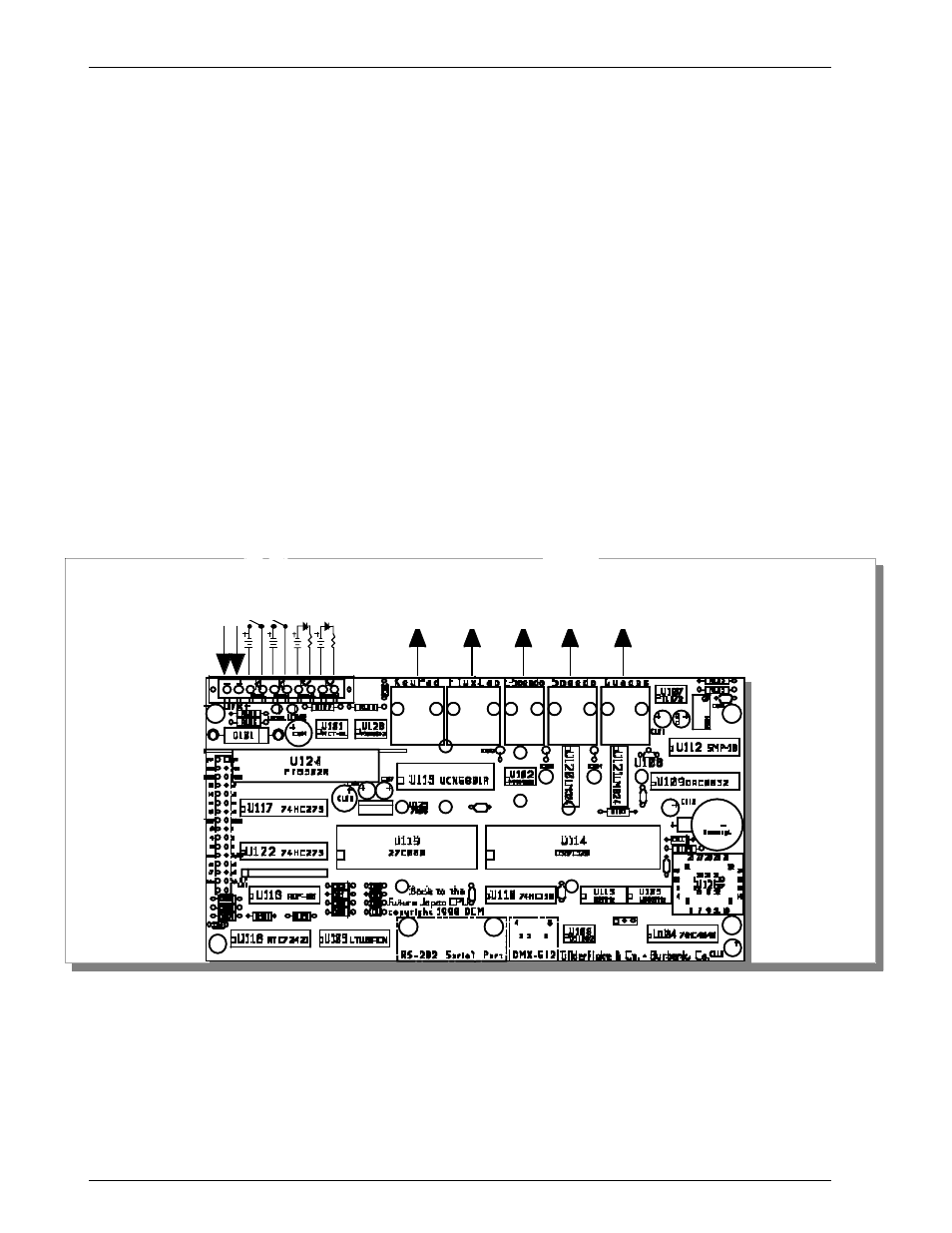
2) CPU: This is a 3.25” x 6.15” printed circuit board that attaches to the back of the time display.
It contains the DS87C520 microcontroller that runs the whole dashboard.
Serial Port
for setting
Clock
DMX-512 for
Programming
and testing
Four
Digitals
RJ-45
Three
Digitals
RJ-45
Serial
RS-422
data
RJ-08
two
analogs/
one
PWM
RJ-12
Three
analogs
RJ-12
15 VDC
Start Show 1
Start Show 2
Status 1
Status 2
The 32 MHz oscillator runs the microcontroller and baud clock for the DMX-512 input. The
1.8432 MHz oscillator provides the time base for the show playback (at 30 FPS), low speed se-
rial port, and display multiplexing. All socketed ICs are held in place by pull ties.
Show memory is contained in a single thirty-two pin Eprom (27C040). The show data is
based on the program we created for Universal Studios, Hollywood. Several channels have
been added for the additional analog and digital channels used on the Back to the Future
G
ILDERFLUKE
& C
O
. • 205 S
OUTH
F
LOWER
S
TREET
• B
URBANK
, C
ALIFORNIA
91502 • 818/840-9484 • 800/776-5972 •
FAX
818/840-9485
E
AST
C
OAST
/F
LORIDA
O
FFICE
• 7041 G
RAND
N
ATIONAL
D
RIVE
• S
UITE
128d • O
RLANDO
, F
L
32819 • 407/354-5954 •
FAX
407/354-5955
2