Remove heat sink, Remove processor card – Sonnet Technologies Encore_ST G4 Duet 1.7 GHz Processor Upgrade Card User Manual
Page 13
11
Figure 34
Figure 33
Figure 32
Figure 31
screw
heat sink
screw
processor card
clip
clip
processor
card
screw
fan
assembly
2-pin
connector
processor
card
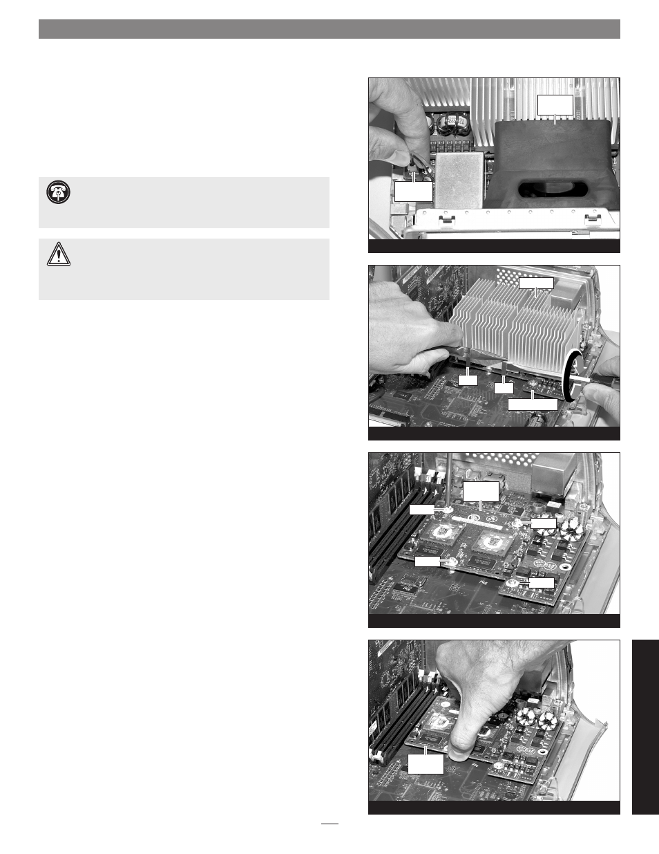
Installation—QuickSilver 2001 and 2002 Models
2. Locate and carefully disconnect the 2-pin fan power connec-
tor from the logic board, and then lift out the fan assembly
(Figure 31).
Remove Heat Sink
With the front of the computer facing you, locate the clips securing
the heat sink to the processor card
(Figure 32). Carefully insert a
flat blade screwdriver between the right clip and the edge of the heat
sink;
do not touch the edge of the processor card. Using extreme
caution, press down on the edge of the clip with needle-nose pliers,
and twist the screwdriver to unhook one side of the clip from the
processor card
(Figure 32). Repeat the procedure on the other side of
the clip. Repeat these steps with the left clip. Once the clips have been
unhooked, gently lift the heat sink and clips away from the processor
card and set them aside, but not on the logic board.
Remove Processor Card
1. Remove the four screws securing the processor card to the logic
board
(Figure 33).
2. Grasping its edges, gently lift one edge of the processor card to
separate it from the logic board, and then carefully lift it straight
up and away
(Figure 34).
Support Note:
The following steps address the removal of
your system’s processor card heat sink. Please note, the dual
processor heat sink is pictured, but the procedure to remove the
single processor heat sink is identical.
WARNING:
Verify that the power cord is disconnected from
your Power Mac before you remove the heat sink and proces-
sor card. The original processor card is secured to the logic board
with four screws, one of which carries +12V and could spark if it is
grounded when the system is on.
Qu
ic
kS
ilv
er
2
00
1/
20
02
screw