Securitron PSM_Series User Manual
Page 4
PN# 500-16200
Page 4
Rev. D, 08/11
Terminal F1 of the power supply connects to terminal F1 of the PSM. This terminal supplies +V
in constant fashion. It serves to power the PSM and also provides the test point for monitoring
the power supply's output voltage. Terminal R1 of the power supply (or any of the "R"
terminals), connects to terminal "-" of the PSM to provide a negative DC return. Terminal B+ of
the power supply is the charge output that normally connects directly to the Battery "+"
terminal. It must no longer connect to the Battery "+" terminal but instead should
connect to terminal B+ in the PSM. The Battery "+" terminal from the power supply
battery pack must connect only to terminal "Battery +" in the PSM. By breaking the
former +DC connection from the power supply to its battery, the PSM is able to take the battery
off its charge terminal in order to conduct its periodic battery testing. Naturally, the battery
negative terminal remains connected to terminal "B-" of the power supply. This is not shown as
it does not represent a change. All power supply to load connections are unchanged by
the addition of the PSM to the installation.
There are three sets of SPDT contacts which are furnished dry on the PSM and which are shown
in the drawing. These report "trouble", "on battery" operation and "system disconnect". They
may be used as the customer desires to provide remote monitoring. For example, they may be
connected to an alarm system. Note that the "trouble" and "on battery" contacts are normally
deenergized. They will switch to report a problem. The system disconnect contacts are
however normally energized. They drop out to report system disconnect because the PSM
has no power at that point and would not be able to keep the associated relay energized. So,
for example, if you wanted a closed loop to open to indicate system disconnect, you would use
the C and NO terminals as these are closed (energized) in the normal condition.
5.2 SYSTEM DISCONNECT WIRING
As has been discussed earlier in Section 4, the PSM will automatically take the batteries off the
load when their voltage has declined below 88% of nominal. This will fully depower the load as
the batteries are the only source of power when they have discharged to that point. It is
generally best that this disconnection occurs as electronic systems should not be operated at
indeterminate voltages well under their specified requirements. Note that it is also possible that
the power supply has experienced a defect which has caused it to output a dangerously low
voltage. Since system disconnect separates the load from both the power supply output and the
batteries, it will deal with any problem that produces a low, indeterminate voltage.
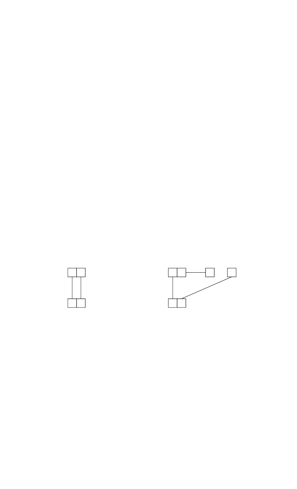
FIG. 2: ADDITIONAL CONNECTIONS FOR SYSTEM DISCONNECT
F1 F2
F1 F2
POWER SUPPLY
PSM
F1 F2
F1 F2
POWER SUPPLY
PSM
C
NC
FIRE ALARM REL
SYSTEM DISCONNECT
WIRING WITH NO OTHER
SYSTEM RELEASE
SYSTEM DISCONNECT
WIRING WITH FIRE ALARM
SYSTEM RELEASE
Refer to Figure 2. Terminal F1 in the PSM receives +V power directly from the power supply.
Terminal F2 in the PSM connects to F1 in the PSM via an internal 10 Amp relay contact which is
closed in the normal condition. So in the normal condition, terminal F2 in the PSM can output
+V. In system disconnect, the connection between terminals F1 and F2 in the PSM opens, so
there is no voltage on F2.
Securitron power supplies have constant +V on their terminal F1 and their terminal F2 connects
to the load through the power supply circuit breakers. Therefore, for any Securitron power
supply to drive its load, terminals F1 and F2 in the power supply must be connected. This can
be done as is shown in the left side of Figure 2. This connection allows the PSM to release the
load in system disconnect. However, the installation may require additional release contacts. In
a magnetic lock installation, this is generally fire alarm auxiliary latching NC contacts. The right