American DJ Verti-Pro II User Manual
Page 4
VER
TI PRO II™
Operation
©
American DJ
®
- www
.americandj.com - VER
TI PRO II™ Instruction Manual Page 7
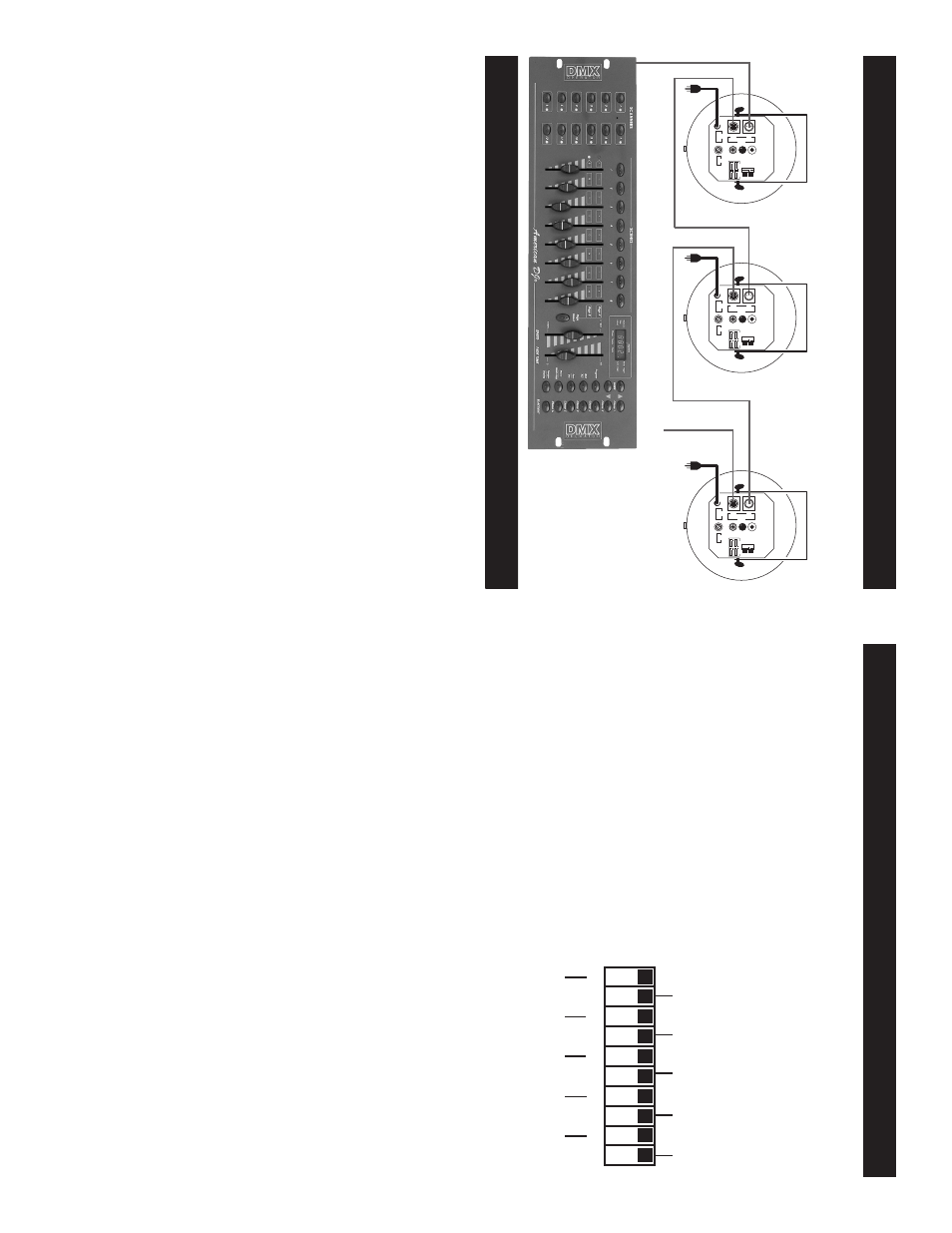
To
next DMX unit or terminate.
T
ypical DMX Linking:
©
American DJ
®
- www
.americandj.com - VER
TI PRO II™ Instruction Manual Page 8
VER
TI
PRO
II™
Set
Up
be placed anywhere in a DMX line, at the beginning, at the end, or
anywhere in the middle. When a fixture is assigned a DMX address of
1, the DMX controller knows to send DA
T
A
assigned to address 1 to
that unit, no matter where it is located in the DMX chain.
Dip-switches in DMX mode:
This unit uses dip switches to assign a
DMX address. Each dip switch represents a binary value.
Dip Switch 1 address equals 1
Dip Switch 2 address equals 2
Dip Switch 3 address equals 4
Dip Switch 4 address equals 8
Dip Switch 5 address equals 16
Dip Switch 6 address equals 32
Dip Switch 7 address equals 64
Dip Switch 8 address equals 128
Dip Switch 9 address equals 256
Each dip switch has a preset value.
A
specific DMX address is set by
combining the dip switches that sum your desired value. For example:
To
achieve a DMX address of 21, combine dip switches 1, 3, and 5.
Sense dip switch 1 has a value of 1, dip switch 3 has a value of 4,
and dip switch 5 has a value of 16, the combination of the create a
DMX value of 21.
Set DMX address 21:
Set DMX address 201:
Dip-switches # 1 = 1
Dip-switches # 1 = 1
3
= 4
4 = 8
5
= 16
7 = 64
= 21
8 = 128
= 201
Data Cable Requirements (For DMX and Master/Slave Opera-
tion):
The VER
TI PRO II™ can be controlled via DMX-512 protocol.
The DMX address is set using the dip-switches on the rear panel of the
VER
TI PRO II™.
Y
our unit excepts 3-pin XLR connector for data input
and data output (Figure 5). When using a DMX controller with 5-Pin
XLR output jacks or when linking from a DMX fi
xture with 5-Pin XLR
jack to the VER
TI PRO II™, be sure to follow the pin conversion chart
on page 12. If you are making your own cables, be sure to use stan-
ON
19
8
7
6
5
4
3
2
10
128
28
32
256
65
16
4
1
SP
DMX CHANNEL
VER
TI PRO II™
Set Up
Power
Supply:
Before
plugging
your
unit
in,
be
sure
the
source
voltage in your area matches the required voltage for your
American
DJ
®
VER
TI PRO II.™ Because line voltage may vary from venue to
venue, you should be sure your unit voltage matches the wall outlet
voltage before attempting to operate you fi
xture.
DMX-512:
DMX
is
short
for
Digital
Multiplex.
This
is
a
universal
protocol used as a form of communication between intelligent fixtures
and controllers.
A
DMX controller sends DMX data instructions from
the
controller
to
the
fixture.
DMX
data
is
sent
as
serial
data
that
travels from fi
xture to fi
xture via the DA
T
A
“IN” and DA
T
A
“OUT” XLR
terminals
located
on
all
DMX
fi
xtures
(most
controllers
only
have
a
DA
T
A
“OUT”
terminal).
DMX Linking:
DMX is a language allowing all makes and models of
dif
ferent manufactures to be linked together and operate from a single
controller
, as long as all fi
xtures and the controller are DMX compliant.
To
ensure proper DMX data transmission, when using several DMX
fixtures try to use the shortest cable path possible.
The order in which
fixtures
are
connected
in
a
DMX
line
does
not
influence
the
DMX
addressing. For example; a fixture assigned a DMX address of 1 may
MINI/C ONLY
SENSITIVITY
MIC.
DMX Indicate
Black = Live
White = Neutral
Green = Earth
Power
120 V / 10 A
240 V / 5 A
Fuse
ON
Master
ON
Head 1-CH 1
ON
ON
Head 3-CH 3
Head 2-CH 2
Master/Slave Chart
1
2
3
4
5
6
7
8
9 1
0
ON
1
2
4
8
16
32
64
128
256
M / S
1 = Grand 2 = Data - 3 = Data +
DMX Out
DMX In
DMX Link