American DJ Verti-Pro II User Manual
Page 3
Operating
Modes:
You
can
operate
the
VER
TI
PRO
II
™
in
three
different modes:
•
Stand-Alone mode (Usually for single unit operation) -
The unit
will react to sound, chasing through the several built in programs.
You can also use the optional V
ertiPro/C remote control to blackout
the unit.
•
Master/Slave
mode
-
Allows
you
to
daisy
chain
up
to
4
fixtures
together
for
a
synchronized
light
show.
The
fixtures
will
react
to
sound chasing through several built in programs.
You can also use
the
optional
V
ertiPro/C
remote
control
to
change
programs
and
blackout the units.
•
DMX control mode -
This function will al
low you to control each
fixtures
DMX
traits
with
a
standard
DMX
512
controller
such
as
the American DJ
®
Show Designer™ or DMX Operator
.
™
NOTE:
Stand-Alone
and
Master/Slave
operation
require
a
sound
source to operate properly. The units will blackout to conserve lamp
life when inactive for more than 60 seconds.
A
single sound source
will reactivate the units.
Stand Alone Mode:
1.
To
operate
a
single
unit
or
several
units
as
individuals
in
stand
alone
mode,
turn
dip
switch
number
10
to
the
on
position
(see
page 13) and plug the unit(s) in.
If you are running more than one
unit in stand alone mode do not link the units together
.
2.
Adjust
the
sensitivity
knob
on
the
bottom
of
the
unit
so
the
unit
will react to sound and cycle through the internal chases.
T
u
rning
the sensitivity knob in a clockwise direction will make the fixture
more
sensitive
to
sound,
turning
the
sensitivity
knob
in
counter-
clockwise direction will make the fixture less sensitive to sound.
Master-Slave Operation (Sound
Active):
In Master-Slave opera-
tion one unit will act as the controlling unit, the others will react to the
controlling units programs.
Any unit can act as a master or a slave.
1.
Using standard XLR microphone cables, daisy chain your units
together via the XLR connectors on the rear of the unit. Remem-
ber the Male XLR connector is the input and the Female XLR is the
output.
The fi
rst unit in (master) will use the female XLR connector
only. Refer to the set-up procedures beginning on page 8.
2.
Follow
the
Master-Slave
dip-switch
chart
on
page
13
for
proper
VER
TI PRO II™
Operation
dip-switch settings.
3.
The
optional
V
ertiPro/C Blackout Controller
may be used in this
operation mode to control a blackout function.
4.
After the unit settings have been set and are plugged in, adjust
the sensitivity knob on the rear of the master unit to make them
react to sound.
Universal DMX Control:
Operating through a DMX controller allows
the
freedom
to
create
unique
programs
tailored
to
one’
s
individual
needs.
1.
The VER
TI PRO II™ uses one DMX channel.
This channel con-
trols the rotation of the unit’
s
internal wheel. Please refer to page
14 for a detailed description of the DMX traits.
2.
T
o
control your fixture in DMX mode, follow the unit set-up proce-
dures
beginning
on
page
8
as
well
as
the
set-up
specifications
that are included with your DMX controller
.
3.
Use the controller
’s
faders to control the various DMX fixture traits.
4.
This will allow you to create custom programs.
5.
When using a DMX controller and setting up for DMX operation
follow the dip switch settings on page 13.
6.
For help operating in DMX operation consult the manual included
with your DMX controller
.
7.
For longer cable runs (more than a 100 feet) use a terminator on
the last fixture in you DMX chain.
VER
TI PRO II™
Operation
©
American DJ
®
www
.americandj.com VER
TI PRO II™ Instruction Manual Page 5
©
American DJ
®
www
.americandj.com VER
TI PRO II™ Instruction Manual Page 6
MINI/C ONLY
SENSITIVITY
MIC.
DMX Indicate
Black = Live
White = Neutral
Green = Earth
Power
120 V / 10 A
240 V / 5 A
Fuse
ON
Master
ON
Head 1-CH 1
ON
ON
Head 3-CH 3
Head 2-CH 2
Master/Slave Chart
1
2
3
4
5
6
7
8
9 1
0
ON
1
2
4
8
16
32
64
128
256
M / S
1 = Grand 2 = Data - 3 = Data +
DMX Out
DMX In
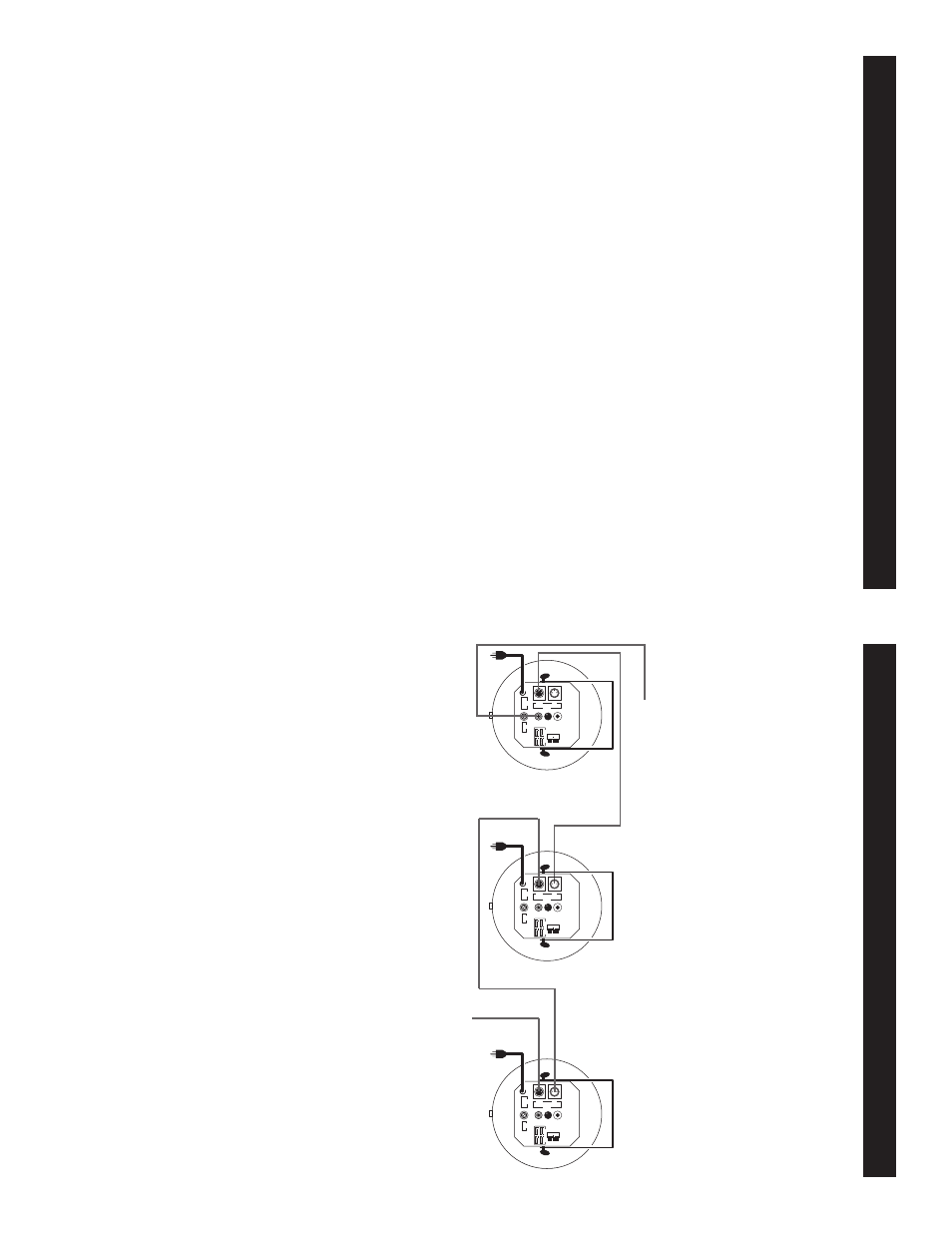
DMX Link
For a more dramatic effect, link several Color units together
.
Master/Slave Linking:
To
next VER
TI PRO II™ if applicable
Optional V
ertiPro/C or V
ertiPro/C blackout controller
MINI/C ONLY
SENSITIVITY
MIC.
DMX Indicate
Black = Live
White = Neutral
Green = Earth
Power
120 V / 10 A
240 V / 5 A
Fuse
ON
Master
ON
Head 1-CH 1
ON
ON
Head 3-CH 3
Head 2-CH 2
Master/Slave Chart
1
2
3
4
5
6
7
8
9 1
0
ON
1
2
4
8
16
32
64
128
256
M / S
1 = Grand 2 = Data - 3 = Data +
DMX Out
DMX In
DMX Link