Hrv and erv typical installations, Semi ducted system ( for superior series only), Fully ducted system – Reversomatic Economy Series User Manual
Page 9
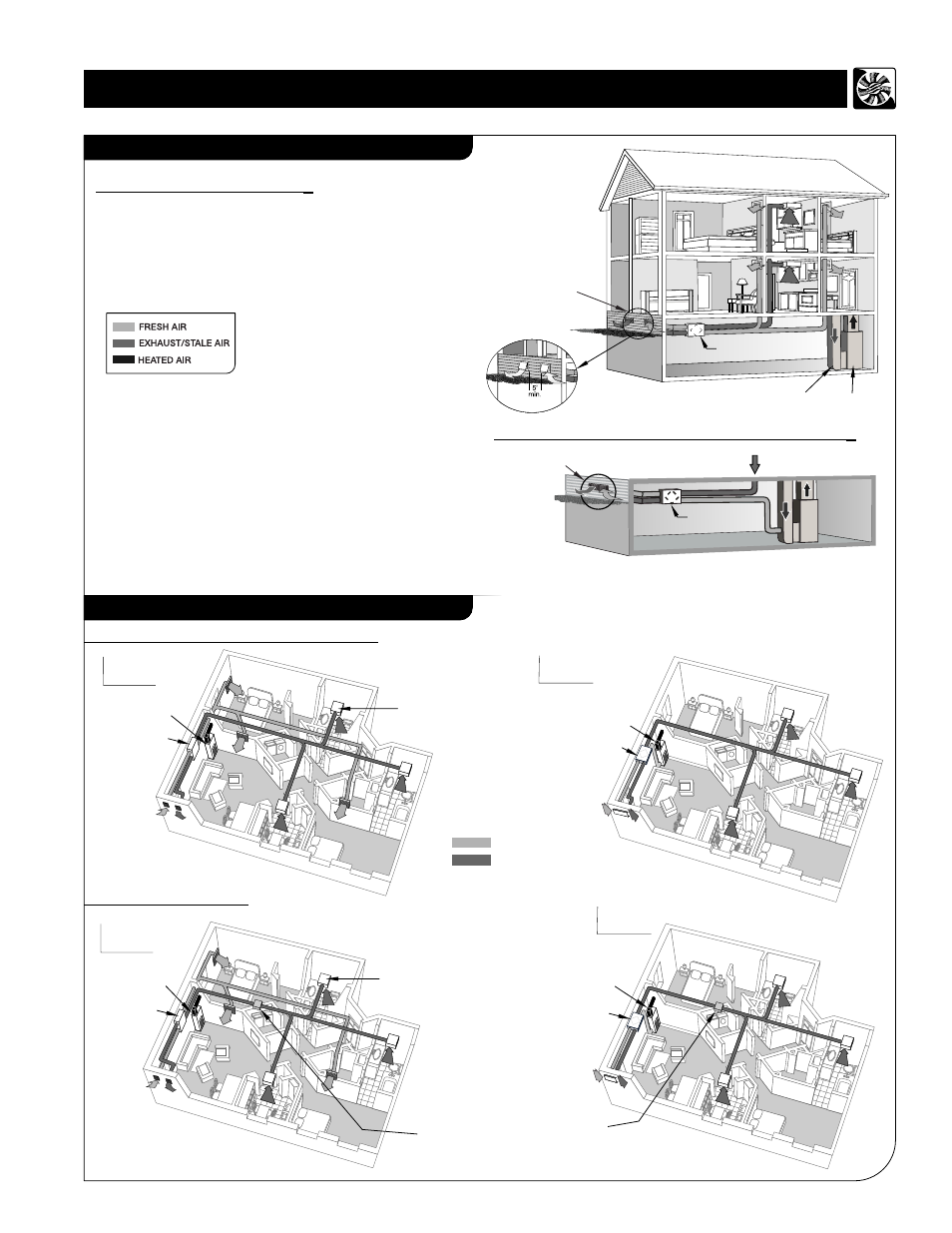
HRV and ERV Typical Installations
7
2 Single Vents
SVE-50 and SVI-50
Shown, 5 ft. minimum
gap between vents
“Fresh Air/ Exhaust Air
Vents Installation”
HRV/ERV (SUPERIOR)
RETURN-AIR DUCT
FURNACE
Wall Cap
Exhaust/Intake
WCE-5, WCI-5
shown
• This installation enables stale air to be drawn from the
poorest air quality areas of the home (washrooms & kitchen)
Double Vent with Extruded Aluminum Grille
DVG200 shown “Fresh Air/Exhaust Air Vent installation”
from washrooms
and kitchen
Semi Ducted System ( For Superior series only)
• It is recommended that the furnace blower run
continuously or HRV/ERV operation be interlocked
with the furnace blower to evenly distribute the fresh
air throughout the house.
• A backdraft damper is required in the fresh air exhaust side
to prevent outdoor air from entering the unit when the
Furnace / Air handler is running and the unit is in Standby,
OFF or in defrost mode.
Note: (For Semi Ducted System only)
Typical Installations for House
Installation Options for High-Rise Condominium
Fully Ducted
System
With Fan-Coil
System
FRESH AIR
EXHAUSTED AIR
Balancing Box
Fan-coil Unit
HRV/ERV
Fan-coil Unit
HRV/ERV
NOTE:
For Project Series use single bathroom
exhaust fan or inline bathroom exhaust fan
(for two washrooms).
This is a stand alone HRV/ERV system which is not
connected to a force air system. Stale air is drawn from
key areas of the home (bathroom, kitchen) while fresh
air is supplied to main living areas.
Fully Ducted System
(for Superior series only)
Note:
All Vents must be installed
min. 5 ft away from sidewalls.
Balancing Box
With Fan-Coil
System
Fully Ducted
System
Fan-coil Unit
HRV/ERV
Fan-coil Unit
HRV/ERV
Project series shown
Superior / Project Condo Series Shown
HRV/ERV (SUPERIOR)
Model #
RHRV-S100A
RHRV-S100P
RERV-S100
RHRV-C100A
RHRV-C100P
RERV-C100
Model #
RHRV-P100A
RHRV-P100P
RERV-P100