Control board, Option 2, Or a) b) c) d) – Reversomatic Economy Series User Manual
Page 7: Light / switch option
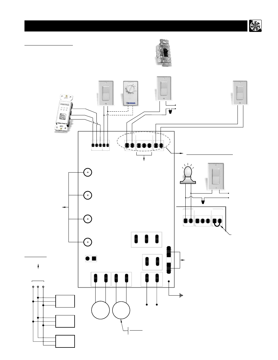
Wiring Diagram (Superior, Project Series and Project Condo Unit)
5
CONTROL BOARD:
a) Timer Switch (TC100)
b) Wall Switch
c) Dehumidistat
d) Time Delay Switch
e) Master On/Off Switch
for HRV/ERV
f ) Light
Optional Accessories (Not Supplied)
F
AN2
F
AN1
LINE
NEUTRAL
PUSH FOR F
AN
M I N U T
E S
or
a)
b)
c)
d)
Hi
Low
Light / Switch Option
120 Vac / 1 / 60Hz
Power Supply
Hi
Low
Furnace, Fan Coil,
Heat Pump
Interlock
4 - Speed Controller for Manual Balancing
and
Air Flow
Adjustment
120 VAC / 1 / 60Hz
Power Supply
Ground
Fuse
On
Off
e)
Low
High
Low
High
Exhaust
Fan Speed
Supply
Fan Speed
Supply Fan Exhaust Fan
b)
Temp. Sensor
Safety Switch
Low Voltage
+5
DA
T
C
Speed
Contact
L0/HI
SPEED
HV INPUT
Remote
0n/0ff
HV
NC
C
N0
Ext. Interlock
HIGH VOLTAGE
Damper Interlock
NC
C0M
N0
f)
HRV/ ERV
Hi / Low
Light
On / Off
120 Vac / 1 / 60Hz
Power Supply
Jumper
(remove jumper to install
master ON/OFF switch)
b)
L0/HI
Speed
HV Input
Remote
0n/0ff
HV
NC
C
N0
Ext. Interlock
HIGH VOLTAGE
FAN # 1
FAN # 2
FAN #2 - Single speed
(Bathroom Exhaust fan connection for “Project Series”)
Note:
Up to 3 Timer Switches (TC100)
can be connected to control
board of HRV/ERV by using
three 28 AWG (min.) Stranded
Copper wires. (see option 2)
Option 2:
Timer
Switch
1
Timer
Switch
2
Timer
Switch
3
to Control
Board
Note:
Make sure, the
Line must be connected to
Line and Neutral connected to Neutral.
Unit will not function if not connected correctly.
RED
YEL
GND
RED
YEL
GND
C
+5
DAT
RED
YEL
GND
RED
YEL
GND
Model # RHRV-P100A
RHRV-P100P
RERV-P100
Note: Same power source should be
used for wall switch and HRV
/ ERV