Hrv and erv typical installations (cont’d) – Reversomatic Economy Series User Manual
Page 11
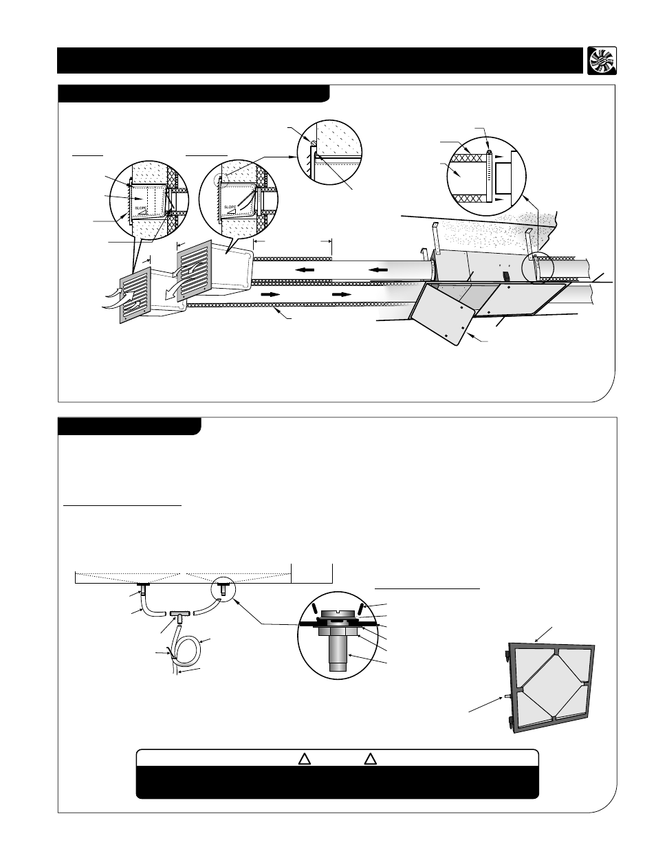
Drain Connection
During defrost cycle the HRV unit may produce some condensation and the water should flow into a nearby drain.
The HRV cabinet has pre-punched holes for the drain, in order to keep the drain pan intact
hand tighten the 2 plastic drain
tube to the unit using the gasket and nuts.
Cut two sections of ½" drain pipe and connect the other ends to the drain tube then connect to “ T ” connector. Connect a
drain line and create a
P-trap to prevent the unit from unpleasant odours from drain source. Tape or fasten base to avoid
any bends.
The HRV and all condensate lines must be installed in a space where the temperature
is maintained above the freezing point or freeze protection must be provided.
CAUTION
!
!
Minimum 5 Feet
(1” Thick)
Intake
Exhaust
Insulation
CAULKING GRILLE
- 3 SIDES ONLY, NOT ON BOTTOM
CAULKING WALLBOX
- CAULK WALLBOX TO
STRUCTURE ON ALL 4 SIDES
Minimum
5 Feet
Metal Clamp
Insulation
Duct
Backdraft
Damper
Grille
Insulation
Wallbox
Access Door
9
Note:
For Horizontal installation,
connect only 1 drain spout assembly on lid / door.
cut one ½’’ drain pipe and connect one end to the drain spout and the other
end to the drain line. Don't forget to create a P-trap as shown above.
For Vertical installation
“ T ” Connector
½” I.D.
Drain Pipe
Zip Tie
Drain Spout
to Drain
Drain Pan
“P” Trap
Drain Pan
Drain Spout Assembly
Rubber washer
Drain Spout
Nut
Steel washer
HRV/ERV Steel Housing
Plastic Drain Pan
Lid
HRV and ERV Typical Installations (cont’d)
Typical Installations of Single Vents & Access door
(For vertical installation)
Use this drain for
horizontal installation
Fresh air intake and supply duct must be totally insulated. Exhaust duct
must be 5 feet insulated. In colder climate, it is recommended to insulate
all exhaust and supply ducts.
Note:
Note:
Use appropriate access door size for easy access and
routine maintenance of the unit. For more info visit
http://www.reversomatic.com/HRV&ERV/Accessories