Archive, Opera, Opera operation tion tion tion tion – Ransburg AirTronic 79053 User Manual
Page 9: Modes of i/o, Airtronic - operation
LN-9241-02.1
AirTronic - Operation
6
6
6
6
6
MODES OF I/O
MODES OF I/O
MODES OF I/O
MODES OF I/O
MODES OF I/O
The
AirTronic System
AirTronic System
AirTronic System
AirTronic System
AirTronic System may be run in three
different I/O modes:
1. Local
2. External Discrete signals
3. Remote I/O via the Serial Node Adapter, and
Serial Node Adapter Plus Module
Local Mode
Local Mode
Local Mode
Local Mode
Local Mode
All I/O is via Display Module front panel. The front
panel knob sets the flow Setpoints for each channel.
In the full CCW position, this control has a detent
and in this detent position the module accepts a
Setpoint from the Node Adapter or external discrete
signals. (See Figure 1)
The front panel display information is determined
by the SELECT
SELECT
SELECT
SELECT
SELECT push button. On power-up, the
display for each channel reads actual flow in
standard liter/minute (SLPM) in that channel. The
LED
LED
LED
LED
LED under the ACT
ACT
ACT
ACT
ACT (Actual) label is illuminated. If
the SELECT
SELECT
SELECT
SELECT
SELECT button is pressed once, the LED
LED
LED
LED
LED
under the SET
SET
SET
SET
SET label is illuminated and the display
reads that channel's setpoint. If the SELECT
SELECT
SELECT
SELECT
SELECT
button is pressed once more, the LED
LED
LED
LED
LED under the
STS
STS
STS
STS
STS (Status) label is illuminated, and the display
provides status information. (See Status Conditions
section for status code information.) If the SELECT
SELECT
SELECT
SELECT
SELECT
button is pressed once more, the display goes
back to the actual flow condition.
Figure 3: Local Canbus Signal Connection
Figure 3: Local Canbus Signal Connection
Figure 3: Local Canbus Signal Connection
Figure 3: Local Canbus Signal Connection
Figure 3: Local Canbus Signal Connection
All Local Canbus Communication between the
AirTronic Module to the RemoteUnit Back panel
is via discrete wiring to the 8-pin terminal strip on
the motherboard. Motherboard 78145-00 uses J9
and J12. Motherboard 78147-00 uses J5, J8, and
J11.
Figure 2: Internal Remote Panel Connections
Figure 2: Internal Remote Panel Connections
Figure 2: Internal Remote Panel Connections
Figure 2: Internal Remote Panel Connections
Figure 2: Internal Remote Panel Connections
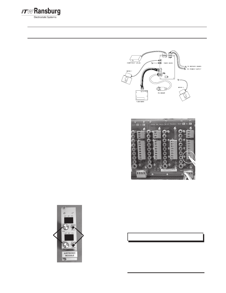
Figure 1: Remote Local Modes
Figure 1: Remote Local Modes
Figure 1: Remote Local Modes
Figure 1: Remote Local Modes
Figure 1: Remote Local Modes
OPERA
OPERA
OPERA
OPERA
OPERATION
TION
TION
TION
TION
>
The Display Module Flow Control
The Display Module Flow Control
The Display Module Flow Control
The Display Module Flow Control
The Display Module Flow Control
knob must be in the full CCW "REM"
knob must be in the full CCW "REM"
knob must be in the full CCW "REM"
knob must be in the full CCW "REM"
knob must be in the full CCW "REM"
(remote) position for the module to
(remote) position for the module to
(remote) position for the module to
(remote) position for the module to
(remote) position for the module to
accept flow setpoints from outside
accept flow setpoints from outside
accept flow setpoints from outside
accept flow setpoints from outside
accept flow setpoints from outside
the module.
the module.
the module.
the module.
the module.
N O T E
N O T E
N O T E
N O T E
N O T E
Pin 7(+)
Pin 8 (-)
R e m o t e
R e m o t e
R e m o t e
R e m o t e
R e m o t e
Local Select
Local Select
Local Select
Local Select
Local Select
Select Push
Select Push
Select Push
Select Push
Select Push
B u t t o n
B u t t o n
B u t t o n
B u t t o n
B u t t o n
ARCHIVE