Archive, Airtronic - operation, External discrete signals – Ransburg AirTronic 79053 User Manual
Page 10
LN-9241-02.1
AirTronic - Operation
7
7
7
7
7
P I N
P I N
P I N
P I N
P I N
#
#
#
#
#
S I G N A L
S I G N A L
S I G N A L
S I G N A L
S I G N A L
DESCRIPTION
DESCRIPTION
DESCRIPTION
DESCRIPTION
DESCRIPTION
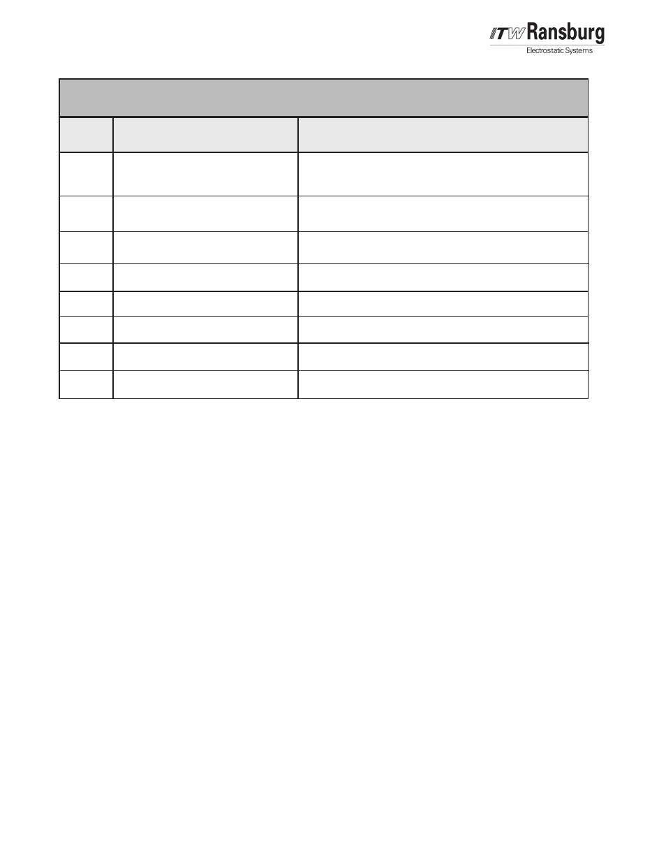
1
2
3
4
5
6
7
8
Channel 1 Analog Set Point *
Channel 2 Analog Set Point *
Channel 1 Trigger
Channel 2 Trigger
Channel 1 Hold
Channel 2 Hold
Serial Bus (+)
Serial Bus (-)
0-10V = 0 To Full Scale
4-20 mA = 0 To Full Scale
0-10V = 0 To Full Scale
4-20 mA = 0 To Full Scale
24 Vdc if Status Condition Is Active **
24 Vdc if Status Condition Is Active **
24 Vdc If Status Condition Is Active **
24 Vdc If Status Condition Is Active **
Serial Bus to Remote Unit
Serial Bus to Remote Unit
EXTERNAL DISCRETE SIGNALS
EXTERNAL DISCRETE SIGNALS
EXTERNAL DISCRETE SIGNALS
EXTERNAL DISCRETE SIGNALS
EXTERNAL DISCRETE SIGNALS
* Set by Display Module SW2, Position 7. (Off = 0-10 Vdc & On = 4 to 20 mA)
** Set by display Module jumper E2
E2 Pins 1 & 2 24V input required (Sourcing)
E2 Pins 2 & 3 Ground input required (Sinking)
T
T
T
T
Triggering Flow
riggering Flow
riggering Flow
riggering Flow
riggering Flow
A Trigger signal and a Hold signal are provided for
each channel. The channel is triggered On with
discrete inputs or from an external PLC. In order
to get air to flow, the AirTronic unit must have an
active Trigger signal with a non-zero set point.
The set point is set on the display card or from an
external PLC. See "Local Mode" in the "Operation"
section for operation of the display card. The
Trigger signal opens the air supply line by
positioning the needle valve with the stepper motor.
The needle valve position is adjusted until the set
point is achieved. The Control loop may take a few
seconds to position the needle valve and stabilize
the flow.
The Hold signal is needed for applications where
relatively quick On-Off triggering is required. The
Hold signal is designed to work with an atomizer
with an air valve to trigger air source. The Hold
signal works as follows:
• The Atomizer and AirTronic are triggered "On".
• The Hold signal is applied.
• The Atomizer and AirTronic are triggered "Off"."
• The airflow stops because the atomizer air
valve is triggered "Off".
• The AirTronic needle valve remains at the
same position, as it was when the Hold was
applied. The pressure in the channel(s) will
rise to inlet pressure.
• The atomizer is triggered "On". The airflow is
immediate. The system will quickly ramp down
to the preset airflow set when the system was
given the Hold signal.
• The Hold signal is removed. The control loop
positions the needle valve to achieve the set
point flow.
• The AirTronic will now open and fully close
fully close
fully close
fully close
fully close
the needle valve upon trigger signal
ARCHIVE