Installation, Mcv 2 installation procedures – Ransburg MCV2 Modular Color Changer A10800-XX_A11077-XX User Manual
Page 20
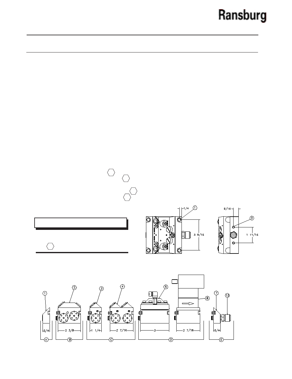
Example: To calculate the footprint of an 6-Color
MCV Assembly:
3/4” (End Plate) + 2-3/8” (purge assembly) +
3-11/16” (8-color valve assembly) + 3/4” (output
assembly) = 7-9/16”
Mounting the Color Changer
There are two mounting configurations as follows:
(Reference Figure 4)
1 5/16” clearance holes for flush mounting
to the booth wall.
2 1/4” x 20 threaded holes in the end blocks.
INSTALLATION
Figure 3: Calculate Footprint
MCV 2 INSTALLATION
PROCEDURES
Determine Location for Color Changer
The color changer should be located as close as
possible to the spray device in order to save paint
and solvent with a color changer. If possible, use an
enclosure to protect the color changer from airborne
paints and solvents.
Calculate Footprint of Color Changer
(See Figure 3)
To calculate the footprint of the color changer add:
• The dimension of the end plate
• The dimension of the purge assembly
• The dimension(s) of the module(s) used to
create the desired number of color valves
• The dimension of the output assembly
A
B
C
E
MCV 2 Collet Series Color Changer - Installation
15
D
NOTE
> If using the optional control devices (regu-
lator and flow meter) include dimension in
calculation above.
Figure 4: Mounting Configurations Footprint
CS-02-01.10